Page 2
|
This page is about an older project of ours. We keep ALL of our projects up on the internet for anyone that's interested...but we are no longer pursuing many of these older ideas. Before starting this project, please check our main Wind Power page to check for similar, more recent designs. These will be the top of the list and flagged with an "active project" tag. If you have any questions about what is current and what is not, or why we no longer work on certain designs, first check out our Wind Turbine Evolution page for a detailed history of how our designs have changed over the years. You can also Email us and we'll fill you in as our email volume permits...check the Evolution page first.
|
PAGE 1
Frame fabrication and alternator design procedures
|
PAGE 2
Frame finishing and alternator fabrication
|
PAGE 3
Alternator and blade assembly
|
PAGE 4
Installation on tower and raising!
|
And, be sure to check out our book Homebrew Wind Power -- it has all the information you need to build this large turbine.
para Español
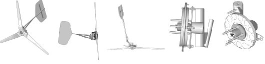
The tail boom is 8.5' long. The pivot on which it's hung is thick walled tubing about 1.8" diameter, and the tail 'bearing' (the part of the tail that slips over the pivot) is from 2" pipe which is reinforced around the slot that determines its 'normal' position.
Pictured above the tail is hung on the machine, it's in the 'normal' (unfurled postion).
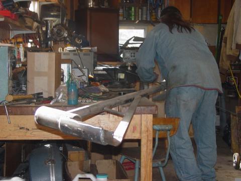
Here we are putting the tail in the 'furled' position and measuring the gap between the tail boom, and the yaw bearing so that we can make a steel 'bumper' which we'll weld to the tail boom. This 'bumper' contacts the yaw bearing (the part that slips over the tower top) when the machine is furling to make certain that the tail cannot swing up so far that it collides with the blades. Once that's welded on, all the 'metal work' is completed.

I use an old HVLP spray gun to apply some good self etching primer and acrylic enamel to the machine, and the magnet rotors.
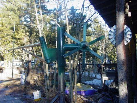
The machine came out looking nice in dark green. I painted the magnet rotors yellow.
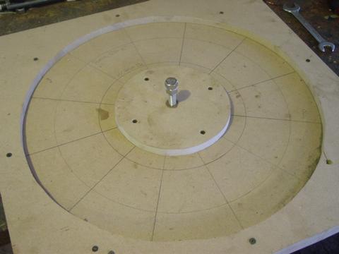
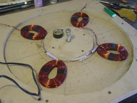
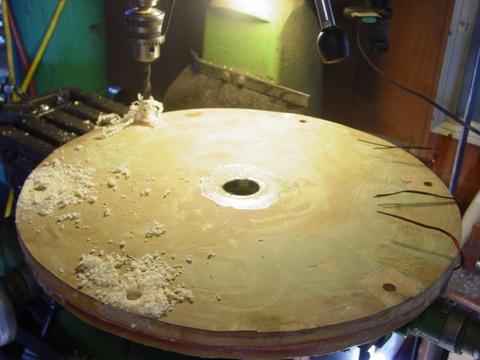
Above is pictured the finished stator mould. It has the correct position for the coils laid out inside it. In the middle we have a 1/2" diameter 'stud' so that we can clamp down the center of the lid when were casting. Around the outer diameter of the mould we use 4 C clamps while casting. The mould will make for a stator that's 20" in diameter and 5/8" thick. The hole in the center will be 7" diameter.
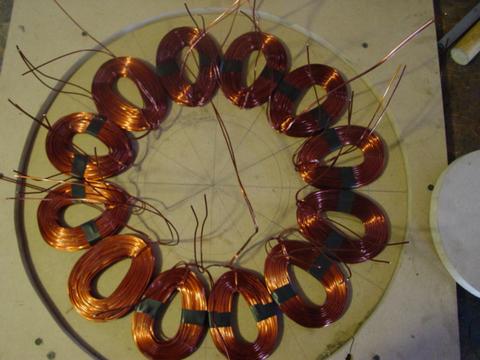
Here we have the 12 coils in the stator. You can see they fit pretty tightly - they are wound such that the sides all touch, and the the magnets will pass exactly over the holes in the coils. Each coil weighs 1.25 pounds, and is wound from 2 strands of #15 wire, which is equiv. to #12 gage. There are 68 windings on each coil, which should (judging from our test coil) give us a cut-in speed around 75 rpm for a 48 volt system. The total weight of copper in the stator is about 16 pounds. This is much the same as our other machines, we have 3 coils per 4 magnets which makes for a simple/nifty 3 phase alternator. So the magnet rotors each have 16 magnets. It's fun to keep track of magnet weight and copper weight. This machine has about 25 pounds of magnets, and about 16 pounds of copper wire. Smaller 10' diameter machines we build have about 6 pounds of copper and 6 pounds of magnet in them. These number increase exponentually as we go up in prop diameter, because not only do we need a more powerful alternator, but the alternator must be more powerful at a lower speed! As machines start getting larger... things start becoming expensive and heavy. The cost of magnets and wire in this machine alone is over $700.
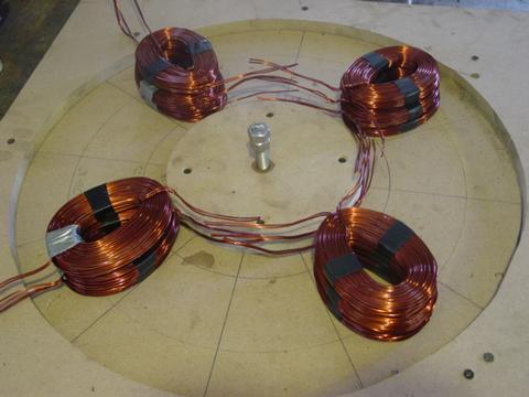
Each phase has 4 coils in series. I like to stack the coils in their positions, and cut the leads to length. It comes out looking tidier if we make all the connections around the inside diameter of the stator. In order to do this, the leads must be cut almost exactly to the right length. Then I strip off the enamel. The easiest way I've found to strip all these wires is with a torch - I heat the wire till it's red hot and all the enamel burns off, and then polish the ends with sandpaper.
Once the ends of the coils are cut to length and stripped, I solder together one phase at a time. It's best to do this in the mould so we know each coil fits in its spot. I cover the solder joints with 'heat shrink' tubing.

After all 3 phases are soldered together, I assemble it all in the mould, and 'force' each coil into exactly its proper place and hold it there with duct tape.
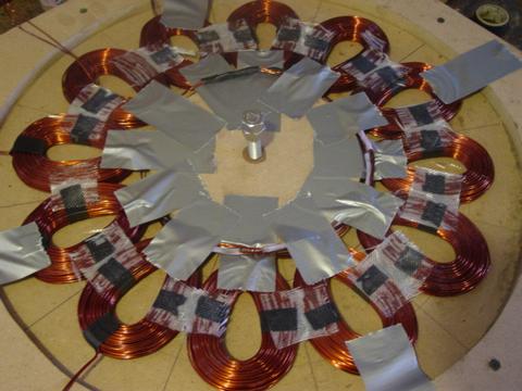
Then I take little square pieces of fiberglass cloth, and glue the coils to each other using those, and super glue. This makes the uncast stator fairly strong so that I can pick it up, take it out of the mould.... without having things come apart.

Here we have removed all the duct tape, and I've tied the ends of each phase together making the 'Star' connection. Next step is to lift this out of the mould, and cast the stator.
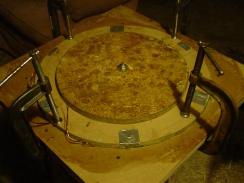
Here we're casting the stator in the mould. I use the standard polyester resin they sell at auto parts stores for fiberglass work. It smells bad, it needs to be handled carefully and a respirator should be used. I like it, other than it's smell - it's cheap, it sets up fast and it seems quite reliable if you follow the directions. The first step in casting is to wax the mould carefully. Automotive 'wax' or Johnsons wood was makes a nice mould release. Then I mix up enough resin to cover the bottom of the mould and wet the sides. Then we put in a layer of fiberglass cloth to strengthen the stator. Then we pour a bit more resin so that the cloth is completely saturated with resin. At this time we carefully take the coils which we glued together in an assembly, and place that in the mould. Then I mix a batch of resin with talcum powder (perhaps a bit less than 50% talc by volume) and pour that into the mould so that the coils are covered by resin. Then another layer of fiberglass cloth, and another layer of straight resin. We make sure the fiberglass is saturated, and try to work out any air bubbles - and then clamp the lid on the mould. For me, if I follow the directions that come with the resin, it usually takes 2 - 4 hours for the resin to harden and cool down at which time the stator can be taken out of the mould. Perhaps better practice is to leave it overnight - but I usually find it's finished in a few hours or less.
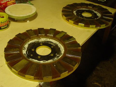
I like to do all the smelly resin work at one time. The magnet rotors are pretty easy, we wrap tape around the outer diameter, and make a plywood 'island' for the inner diameter (8" diameter in this case). I stick the plywood islands down to the steel with caulk so the resin won't leak out. We mix some talcum powder with the resin, and pour it around the magnets. Again - these magnet rotors each have 16 *very* powerful magnets. If they get too close together, or too close to anything made of steel, they'll fly towards it and crash with incredible force. If your fingers got between the magnet rotors I expect you'd lose them. They are *very* dangerous and should be handled *very* carefully and kept in a *very* safe place - there must be no accidents with the magnet rotors! In the picture above they are *too close* together to be safe... I put them that way very carefully for the sake of the picture only, normally I keep them in different places until they're assembled.
Once the stator comes out of the mould, we drill two small holes in it, and screw it to the same template we used to mount the 6 steel stator brackets to the wind turbine. Then we can drill out 6 1/2" diameter holes around the stator and it will fit with the brackets perfectly. It's important to be sure the holes are 'in between' coils so there is no chance of drilling into a coil!
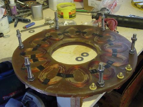
I also drilled out 3 x 3/8" diameter holes in the stator where I mounted some brass bolts which serve as terminals for the electrical connections. Once all the holes are drilled, we mount the 6 studs to the stator for mounting it. It's important to use *all stainless* hardware anywhere near the magnets, so all the hardware pictured above is stainless steel. Otherwise the magnets will be attracted to the studs, and they'll draw flux away from the coils and cause the machine to cog which would make it difficult to balance the blades, and cause it not to start up so easily in low winds.
So there we have it, except for blades, and a tail - all the parts are made and the only work left is assembly.
PAGE 1
Frame fabrication and alternator design procedures
|
PAGE 2
Frame finishing and alternator fabrication
|
PAGE 3
Alternator and blade assembly
|
PAGE 4
Installation on tower and raising!
|