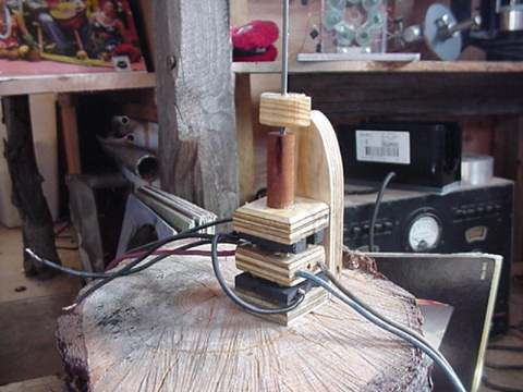
Click the Photo to check out a 15-second MPEG movie (343K) which shows the regulator in operation. Watch close, and you'll see the sudden change on the voltmeter as the regulator changes the wiring of the stator from series to parallel. This is clearly visible both on acceleration of the alternator and deceleration.
This page results from an effort I made to regulate the voltage from permanent magnet alternators. In making wind generators it is important to start with a good low-rpm generator/alternator. Generally, good low-rpm generators require permanant magnets to supply the field. The main reason for this, of course, is if the field of a generator is supplied by electromagnets, they require electricity (inefficient) and simply the space required by copper wire can make it impractical. By using permanent magnets, it is possible to have many strong magnetic poles, packed into a small space so that fairly low rpm can offer a fairly high output voltage.
The disadvantage of permanant magnet generators is that they are difficult to regulate over a range of rpm. In a normal generator or alternator, the voltage is regulated easily, by adjusting it to the field windings. In a permanent magnet machine, the strength of the field is predetermined and fixed simply by the strength of the permanent magnets used. When charging batteries, as in the case of most wind generators, the machine might be very efficient at a certain speed, but at high speeds most of the work done by the propellor is wasted by simply heating up the windings in the generator! For example, in this alternator which I used in this experiment, if all the coils are hooked into series, at 120 rpm it hits 12 volts, open voltage. At 1200 rpm, it's around 120 volts! When charging batteries (12 volts) it runs fairly efficiently at 200 rpm charging aroun 5-6 amps into the batteries. At higher speeds, it charges only a little more, and most of the work into the shaft of the alternator serves only to heat up the windings in the alternator.
If the alternator could be wired differently at higher speeds only, then it could serve efficiently at a wider range of rpm. This voltage regulator works in the following way. The alternator stator is divided into two halves. Depending upon the speed of the alternator, the two halves will be hooked either in series (at low speeds) or in parallel (at high speeds). Such a regulator on any permanant magnet alternator could increase the usable output significantly at both low and high speeds. There is certainly argument that "simpler is better" and it may well be worth the lack of trouble to leave certain machines completely unregulated in the spirit of simplicity and reliability, but - I've thought about this problem for a while since making windmills and this is one possible alternative.
The regulator is really very simple. It consists of a set of contacts which in one position wire the stator in series, and in the other wire the stator in parallel. The whole thing is controlled by some magnets, in close proximity to an Aluminium (Copper would work even better) disc which is mounted to the alternator shaft. Of course, magnets are NOT attracted to Aluminium (or Copper), but...both are very good conductors. Spinning the disc in close proximity to magnets generates current, which is shorted out and has no place to go. This is called the "Lenz Effect." The magnets are pulled (and repelled) by the disc. It is the "pulling" force which is used here. Once the alternator is going a certain speed, the magnets and the electrical contacts they are attached to are physically pulled up to connect to the contacts above - thus re-wiring the two halves of the alternator stator into parallel, halving the voltage and doubling the current. This works exactly like a mechanical Relay, except it is triggered to switch by the Lenz Effect instead of an electromagnetic coil.
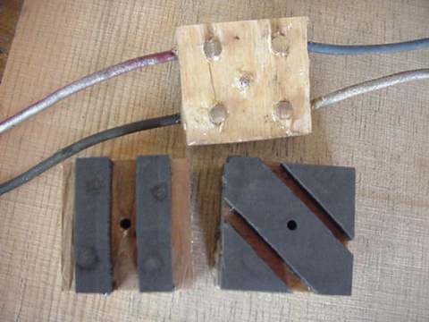
Above are pictured the contacts involved. They are carbon graphite, the same stuff they make motor brushes out of. I cut out the pieces on a saw, and they are arranged to hook two seperate lines (the halves of the stator) into either series (for low rpm) or parallel(for high rpm). The piece with the brass contacts is the moving part and hooks directly to the stator. All the parts are made from plywood. The carbon graphite pieces are super-glued on. I drilled holes in the brass contact and pressed brass rod through them. All were sanded flat with the belt sander. It's very important that they be flat! This would've worked a lot better had I made the brass contacts somehow spring loaded, or flexible, so they could always be assured of making good contact with the carbon. As it is, I'm surprised that it works at all...it actually so far, works very reliably.
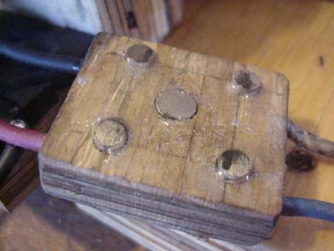
Again, a picture of the moving contacts. Notice the magnet in the center of the block. The rod (1/8" steel) that serves to move the block up and down, is attached ONLY by the force of this magnet. This allows for some flexibility between the block and the rod, to aid in making good contacts between the brass and the carbon. For my first try, I drilled out the block and the rod fit tightly into the brass contact block. I had real troubles getting it to work, and this "flexible magnetic coupling" solved the problem.
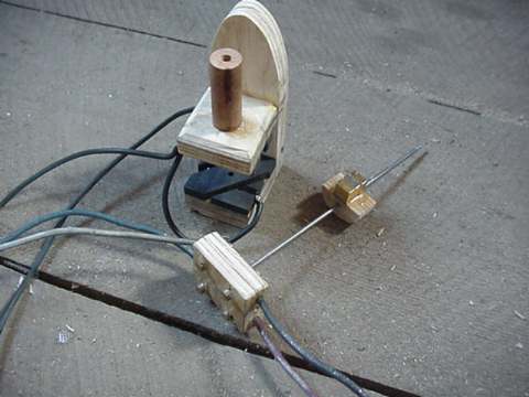
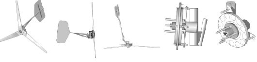
Above are pictured all the parts of the regulator, it's really very simple!
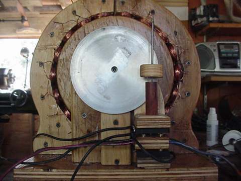
The photo above shows the regulator mounted to the back of the alternator. The Aluminium disc fits just perfectly between the back of the regulator and the magnets. The regulator works pretty well, though lots of little things could be done to adjust it. Changes which would affect performance include: More or less weight on the moving parts, a thicker(or thinner) Aluminium disc, more or less magnets near the disc, and distance between the disc and the magnets. Another thing I did to it (not shown in any pictures) is include a small magnet and a washer which it was attracted to, which serves to pull down on the moving contacts. It helped to insure a tight contact at low rpm, and also a much faster switching action! It actually makes a fast clicking sound, and it never floats between the contacts. As it is adjusted now, when the altnerator comes up from 0 rpm the stator is hooked in series, until it hits around 300 rpm (about 30 volts. It then changes to parallel, and the voltage drops to around 15 and available current doubles. The curve is different on the way down, due mostly to the magnet which holds the bottom contact tightly together. It stays hooked in parallel down to about 10 volts, and then switches back to series and the voltage jumps back up to around 20.
Again, there are a bunch of adjustments that could be made. Simple improvements should definitely include some spring loaded contacts - or some sort of flexibility there. Although my contacts worked in testing, slight wear could render the contacts I made useless. I believe that for currents over 10 amps they should be larger. I was surprised at how hot the carbon graphite got when charging my batteries at 15 amps! Overall though, I think if scaled up some and well made, this sort of regulator could squeeze a good bit of extra power out of an otherwise unregulated alternator, giving better startup performance (starts charging at a lower rpm) and better high-speed performance (halving voltage to double current).
I know there are some alternative, solid-state approaches to solving this problem--but they involve high-power semiconductors, which I can't fabricate in my shop! As we learn more about other approaches we will certainly post information and links. Please let us know via email or our discussion board if you have any ideas or experience with regulating permanant magnet alternators.