
| This page is about an older project of ours. We keep ALL of our projects up on the internet for anyone that's interested...but we are no longer pursuing many of these older ideas. Before starting this project, please check our main Wind Power page to check for similar, more recent designs. These will be the top of the list and flagged with an "active project" tag. If you have any questions about what is current and what is not, or why we no longer work on certain designs, first check out our Wind Turbine Evolution page for a detailed history of how our designs have changed over the years. You can also Email us and we'll fill you in as our email volume permits...check the Evolution page first. |
|
PAGE 1 Stator and Magnet Rotors |
PAGE 2 Assembly and Raising |
PAGE 3 Building Matt's 15 foot turbine |
PAGE 4 Blade Carving -- Matt's turbine |
This page is a diary about the construction of my 14' wind turbine, and some very similar machines currently under construction during the spring of 2004. Click Here to see a more detailed page about the construction of some very similar 10' diameter machines we built during the summer of 2003. As with all the wind turbines we've made, these are pretty experimental. I had my 14' turbine up and down several times before I got it working well, and at the time of writing this it's been up and working well for about 4 months! Could be it'll explode after 5...! To do it over again, I'd make certain parts stronger.
And, be sure to check out our book Homebrew Wind Power for more small wind power information!
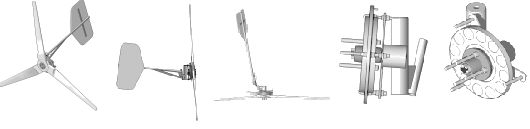
Again, I started with the strut tower from an old Volvo 240 sedan. Here, the main part we're using is the wheel spindle, the hub and bearings, and a bit of the tubing.

Pictured above is the wheel spindle with about 7" of the strut towers tubing attached. Instead of using the strut tower's tubing for the yaw bearing like we did on past machines, this time we'll weld the spindle to a stronger piece of 2.5" diameter pipe.

Most of the metal parts are shown above. There is the piece of 2.5" tubing which serves as the yaw bearing. I used 1" dia pipe for the tail pivot, and there is the 20 deg wedge to set the angle for the tail pivot. This is one thing I'd change now... the strength of the tail pivot worries me a bit after discussing it with Hugh Piggott... but it's done and painted now so time will tell! The magnet rotors for the alternator are 14" diameter and cut from 3/8" thick steel. I had these plasma cut down in town... they cost about $20 ea.

Here we have the yaw bearing, the alternator spindle, and the tail pivot all welded together. The top piece on the yaw bearing is actually the center of one of the magnet rotors which was cutout with a hole saw, it made a nice heavy washer to hold her on top of the tower. The spindle on which the alternator will turn is tipped up a couple deg to help keep the blade tips out of the tower. It adds a bit of insurance and I think it looks kind of sporty that way!

I layed out the positions for the magnets, and the holes through which the studs must fit on a paper disk 14" in diameter. I could then use a center punch to locate the holes I had to machine, and the positions for the magnets.

After it's layed out, I piled up both disks and drilled them at the same time. The center is easy to cutout with a holesaw, the diamter is such that the hub fits through the the hole, I believe it was 2.75".

Above we have the machined rotors and the wheel hub they'll fit onto. There is the large hole in the middle, 5 1/2" dia holes that fit the studs, and then 3 holes (smaller) which are tapped for 1/2" - 13 bolts. These last 3 holes are used for jacking screws which we need to safely put the magnetic rotors together and take them apart. The attraction of these two disks is VERY powerful, wthout jacking screws it would be impossible.

These magnets are rather massive. They are such, that 16 will fit together tightly to form a ring 14" outer diameter and 8" inner diameter. So they are 3" long, about 2.5" wide at the top, and 1/2" thick. I've mounted 12 on each rotor. We might do better here to use a larger disk so that there is some additional space between each magnet, I suspect were having some significant leakage from pole to pole which basicly means were not making best use of the magnets here. With a larger rotor, we could probably build just as powerful an alternator with slightly smaller magnets.
One has to be very careful placing magnets this large! I had already center punched their location, so I was very careful to put each one down, and tap it into place with a copper hammer. One each magnet is placed properly, I superglue them down.

Once the magnets are placed, I wrap duct tape around the outside diameter of the rotors. On the inside I put a greased plywood disk 6" in diameter. The disk, and the tape form a sort of mould so that I can pour polyester resin mixed with a little talcom powder into the rotor up to the thickness of the magnets. I pour it this deep mainly because it looks neat and perhaps makes things a bit stronger, but I think there may be some argument for pouring it perhaps half the thickness of the magnets so that the magnets can serve as little fan blades to help move air around the stator.. that may help with cooling somewhat, I'm not really sure.
It should be stressed... these are VERY powerful magnetic assemblies! Notice how I have them seperated, this is as close as I could safely put these two rotors for a picture! Once done, I handle only one at a time, and hang them somewhere in a safe place. If these two rotors came together I suspect we might never seperate them. If they came together with someones hand in between, I suspect it would break every bone. It's like high explosives if they come together, they need to be treated with similar caution.

Pictured above the back magnet rotor is mounted to the wheel hub. I like to keep the back rotor towards the rear as much as possible, this will keep the hardware that mounts the stator shorter so that it's stronger and more compact. The rotors are held to the hub with 1/2 - 13 allthread and nuts.

I worked out the size of the coils exactly, so that 9 coil would exactly fit around in a circle with no room to spare. The hole in the middle of the coils is just under 3" long. They are somewhat wedge shaped. Here I wound one coil to the proper size from thin wire (Cannot recall, probably #18) and simply counted the number of windings. By poking this coil in the airgap between the two magnet rotors, and knowing the rpm, I could figure out about how many windings per coil would be required to have a proper cutin speed. Once I knew that, I picked the heaviest gage of wire that I could so that the proper number of windings would yeild a coil of the proper size.

There's a picture of a single coil on the coil winder. My 14' machine is for my 12 volt system, so I have 24 windings per coil. It would've worked out to about #9 wire, which is pretty heavy and stiff to wind tightly. So I wound the coils with a bundle of 4 strands of #14 wire, which is close. We're currently building some 24 volt machines, and there we've gone with 48 winding of 2 strands of #14. Im thinking now... that perhaps slightly fewer windings might workout better, so the next stator I make will probably have about 45 windings per coil... things will fit better this way and the cutin speed will be slightly higher. These 24 volt machines will have 15' diameter props.

In the past I've always brought all the wires from each coil to the outside of the stator and done the wiring after the stator was cast. It easy that way, and perhaps it cools a bit better, but I think it looks a little sloppy. So this time we're making all the connections before we cast the stator. To keep the wire a bit shorter (and resistance down slightly) I've made the connections on the inside diameter of the stator. Pictured above I've got 1 phase wired up inside the mould. I do all this in the mould so I know it'll fit!

And here all 3 phases are connected. In an attempt to make it strong enough to move in and out of the mould before it's cast, I superglued little bits of fibrglass mat to the tops of the coils to hold it all together. Again, all the connections are on the inside diameter of the stator, except for the starts, and ends of each phase. Im bringing all those out (6 leads) so that I have the option of either a Star, or Delta connection, although it is my intention to wire it in star and leave it that way.

Once the coils are all wired up, we put them in the mould and cast them in polyester resin with fiberglass mat to strengthen it. Here we have a nice 24 volt stator fresh out of the mould.
Well, thats probably enough pictures to seem rather tedious with a dial up connection, so we'll break this diary into more pages.
|
PAGE 1 Stator and Magnet Rotors |
PAGE 2 Assembly and Raising |
PAGE 3 Building Matt's 15 foot turbine |
PAGE 4 Blade Carving -- Matt's turbine |