| This page is about an older project of ours. We keep ALL of our projects up on the internet for anyone that's interested...but we are no longer pursuing many of these older ideas. Before starting this project, please check our main Wind Power page to check for similar, more recent designs. These will be the top of the list and flagged with an "active project" tag. If you have any questions about what is current and what is not, or why we no longer work on certain designs, first check out our Wind Turbine Evolution page for a detailed history of how our designs have changed over the years. You can also Email us and we'll fill you in as our email volume permits...check the Evolution page first. |
This page is a diary about my latest wind turbine experiment from June of 2003. Although a bit more complex, it features some significant improvements over the brake disk turbines I've made in the past. All the machines I've made in the last two years featured a single magnet rotor with steel laminates, and coils in between. This one is using two magnet rotors turning together with the coils in between. It has some advantages in that there is no loading on the bearings, and no losses in the laminates so it turns very freely. Be patient, there are a LOT of pictures detailing the construction here.
And, be sure to check out our book Homebrew Wind Power for more small wind power information!
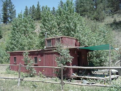
Yesterday my freind and neighbor Dave came up to start building a wind turbine for his small power system. Currently he's got 2 105 watt solar panels setup which do OK, but his site is not excellent for sun. He does have a pretty good wind site up the hill from his caboose. His system is 12 volts, so were building the machine for that.

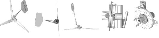
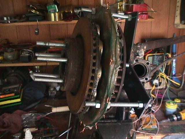
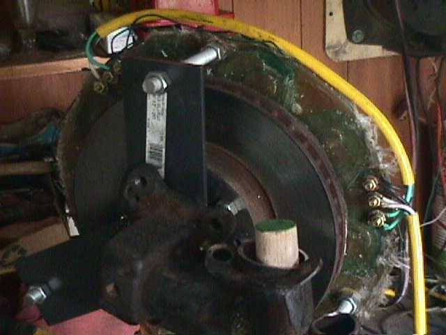
As usual, we started with some Volvo parts (just have too many around....). Were using the front strut asssembly off a Volvo 240, and two 11" diameter brake disks which fit the wheel hub. This machine will be very much like the last one I made. Click here for more details about that. The main change were making here, is that this will be a dual rotor machine. The tail will also be slightly larger and longer. It should be slightly more powerful at lower rpm than mine was, were using slightly more magnet and exactly the same 3 phase stator design as I did last time.
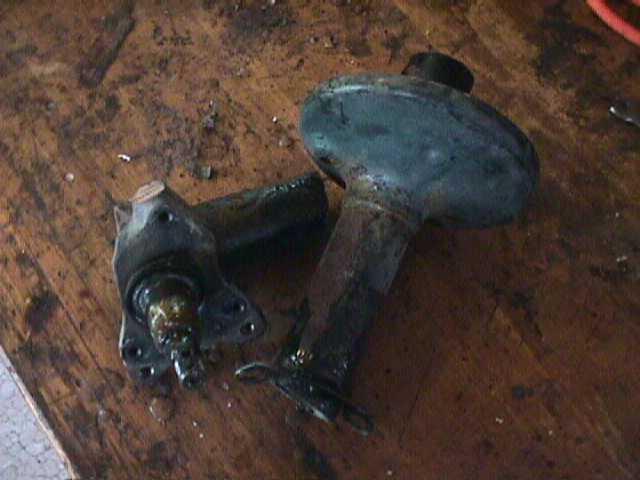
To make the furling tail assembly, I cut the strut about 6" from the wheel spindle. We want the spindle (and therefor the alternator and the prop) to be offset from the tower about 5" to the side.
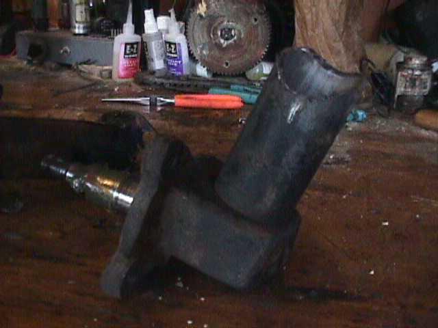
I ground it out so its a good fit for welding. It will be welded on at an angle to provide more contact between the two pieces making the joint stronger. I also like to weld it on so that the spindle (and therefor the alternator and the prop) is pointed up about 2 deg to help keep the tips of the blade away from the tower.
Pictured above you can see what I described a bit better. You can also see the wedge I was setting up on the back side to hold the tail pivot out at about 20 deg.
I like to cut the brake rotors down so that there is a slight lip (about 1/16 inch) to hold the magnets in. This helps a bunch too in spacing the magnets out evenly later. Pictured above Dave is doing this on the lathe.

Here Dave is learning to run the lathe and his friend Fred is cutting up various metal pieces which we'll need.

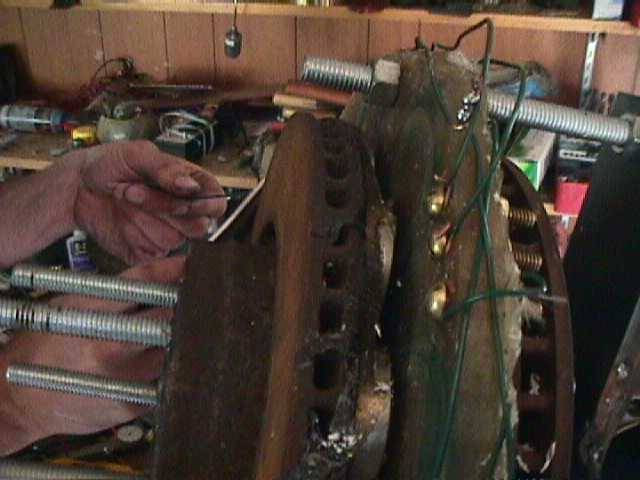
This is how the brake rotors look after cutting them down to make a lip on the outside which holds things together. I don't think this step is necessary - but it's easy and provides some insurance against magnets flying loose. It also makes a nice clean flat surface to put the magnets down onto.
You'll notice that the rotor on the right side has a larger hole in the middle than the one on the left. We turned it out a bit so that this rotor could actually fit on the back side of the wheel hub! (where I put the stator on past machines...). This way the back rotor sits behind the wheel hub with its magnets pointing foward towards the stator.
Here Dave is struggling with strong magnets trying to lay them down with about a quarter inch between each one. They kept sliding together - he was getting a bit frustrated! These magnets are 2" diameter X 1/2" thick. They go down with alternating poles up. Were using 12 of these on each rotor. Once they get placed down and approximately evenly spaced, we used playing cards as shims to make sure the space between each magnet was exactly the same. Its kind of trial and error, but it goes very quickly. Once they are right - a few spots of super glue on each magnet holds them in place untill we pour polyester resin around them.

Since this is a dual rotor machine, the stator will not be able to bolt on in place of the backing plate like I've done in the past. The stator will have to be in between two rotors, and held on by a bracket which ties into the outside of the stator. These are the pieces I made up for this bracket. The bracket will actually bolt on in place of the backing plate (to the strut assy behind the wheel spindle). These 3 pieces are cut from 3/16" thick X 3" wide steel, and they are 7" long.
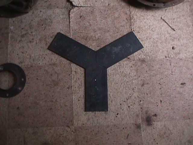
Above you can see how those go together. After this we drilled holes in the center to bolt it down, and a large 1.75" dia hole in the center for the wheel spindle to pass through. We also need to drill holes out at the ends to accept allthread so we can mount the stator to it.

Pictured above Dave is winding up some coils. Just like my last one, each coil occupies the space of about 1 and 1/3 magnets (so 3 coils take up space occupied by 4 magnets, so there are 9 coils in the stator). Its 3 phase, so each phase consists of 3 coils in series. The coils are made up of 65 windings of AWG 14 wire.
Here Dave is putting duct tape around the inner and outer diameters of the magnet rotor. This simply serves as a "quck and dirty" sort of mold, so that we can pour the resin around the magnets and it hopefully wont run out the sides!

Pictured above is the mold we made for the stator, and we're putting some fiberglass fabric in the bottom to strengthen it.

We first poured a bit of resin in the bottom of the mold (got the fabric saturated) and then placed the 9 coils in. Then we cover the coils with more fabric, and pour resin over those and put the lid on the mold.

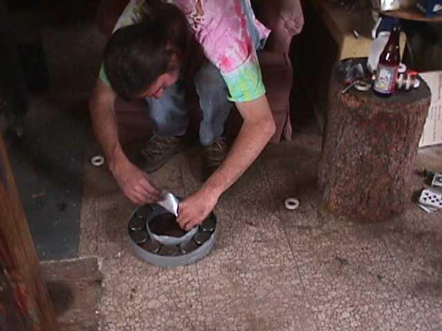
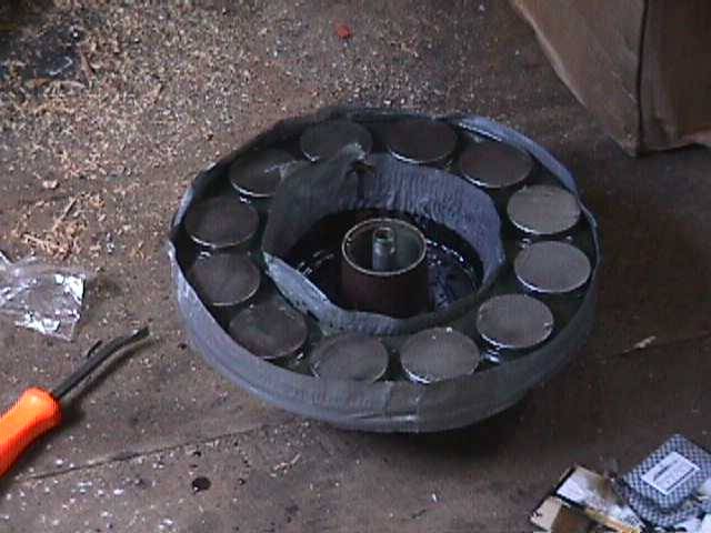
Here we are pouring resin (mixed with talcom powder) into the magnet rotor. Well have to make 2 magnet rotors, but for now we're just doing one. It is possible the alternator will work OK with only one magnet rotor and the other rotor simply serving to conduct the field of these magnets (like laminates except itll be rotating) - so were not doing the 2nd rotor untill we test the alternator. We may even decide to use different magnets on the 2nd one.
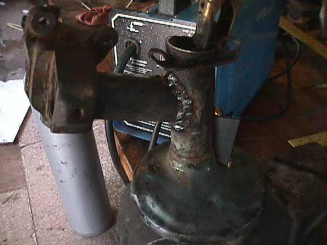
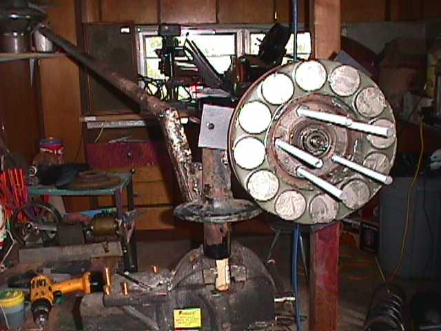
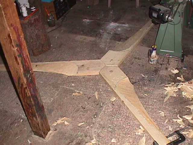
Pictured above the main chassis of the wind turbine is pretty much together. You can see now how the stator bracket bolts on. The tail boom is 5' long.
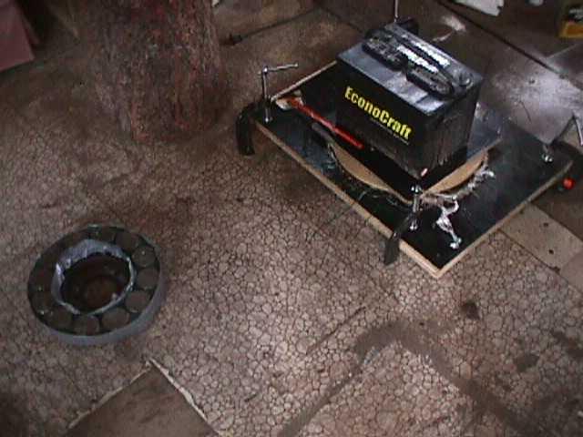
Here you can see the magnet rotor, and the stator mold while the resin sets up. The battery serves as a weight to hold the top of the mold down tightly.

After about 2 hours we opened the mold and took the stator out.
Above you can see how we replaced the studs in the wheel hub with long (10 inches) pieces of allthread. The allthread will serve to hold the magnet rotors, and the prop securely to the wheel hub.
That's where were at after 1 day (About 8 hours of work). You can see things starting to come together! It should be said, this machine is very similiar to the one we built at the SEI Wind turbine workshop on Guemes Island in April. It's very much along the lines of Hugh's Axial Flux Windmill Plans. If I really wanted a guarenteed good machine, I'd probably follow them to the letter, but I like to play with junk I have on hand and experiment a bit. I should also say - again, we have about 8 hours into this so far, and I believe we'll have it completely finished in about 20 hours. But it might come out a bit cleaner, prettier - and possibly a lot better if we took a little more time on certain steps. Time will tell! It's fun though, and since I have limited time to put towards this sort of thing, and Dave only has a few free days available, we're trying to move things along quickly.
Here were putting allthread and nuts into the stator bracket to hold the stator on. The allthread is 1/2" diameter with 13 threads per inch.

Pictured above you can see the notch in the tail hinge which determines the angle of the blade during normal operation and when it's furling in higher winds. We reinforced the pipe around the notch to make things stronger, my guess is it might crack eventually if we didn't.

Here Dave is putting the stator on over the first magnet rotor. It's interesting to note here... with one magnet rotor on the machine, and the 3 long pieces of steel allthread which hold the stator on, that the magnets are somewhat attracted to the allthread and at this point the machine cogs a bit. When we attended Hugh Piggot's seminar in Guemes Island in April, we used stainless bolts for this, so the magnets would not be attracted to it. I kind of wondered if this cogging would get worse with the 2nd magnet rotor on (since there'd be twice the magnets and the top rotor might be getting attracted to the nuts on the front of the stator)... or better, since the magnetic circuit would be completed and the lines of flux would be concentrated between the magnets. As it turned out, when we did put the 2nd magnet rotor on the front of the stator this cogging disappeared completely. I was planning to replace this steel allthread with stainless, but as it turns out I think it is not necessary.
Here we're gluing magnets on the 2nd rotor. It is very important that the 2nd rotor line up perfectly with the 1st one. In other words, wherever we have a North pole facing out on the 1st rotor, we must have a South pole facing it on the 2nd rotor. Keeping in mind that there are 5 studs which hold the 2nd rotor on, we have to take care to position the magnets exactly. What we did, is put the 2nd rotor on without any magnets, and made some marks around it noting the position and polarity of the magnets on the 1st rotor. We then positioned the magnets on the 2nd rotor accordingly. This worked out well.
Here we basicly have the whole alternator together. At this point we could spin the alternator by hand. Were getting about twice the voltage at any given rpm now with two rotors than we were with only one before. We didn't have a tach, or even a clock with a second hand.... so no real numbers yet. But it seems to be hitting cut in voltage (12 Volts) perhaps a bit below 100 rpm.
We soldered all the connections on the stator and made 6 lugs (2 for each phase) from brass screws and brass nuts. It can get tedious stripping all the ends of the magnet wire, a good way is to burn the insulation off with a propane torch, and then sand it lightly.

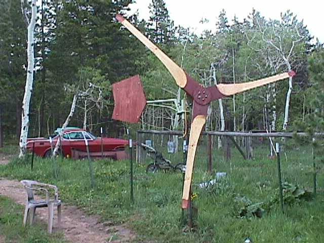
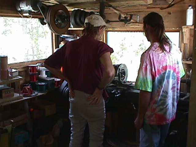
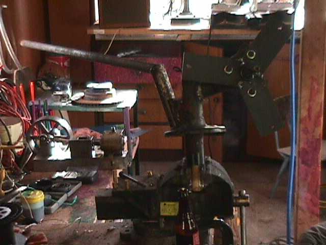
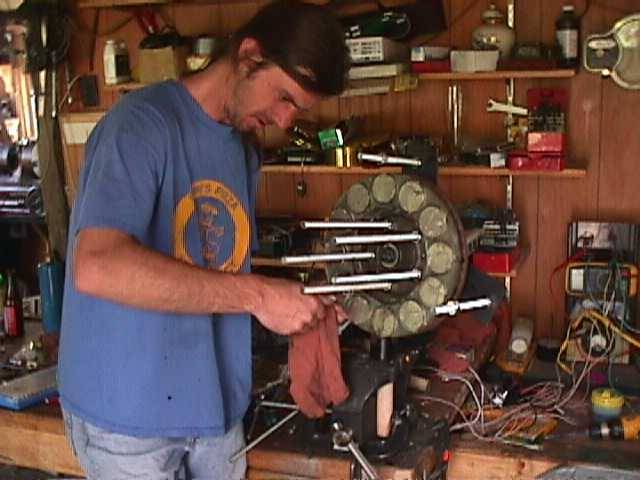
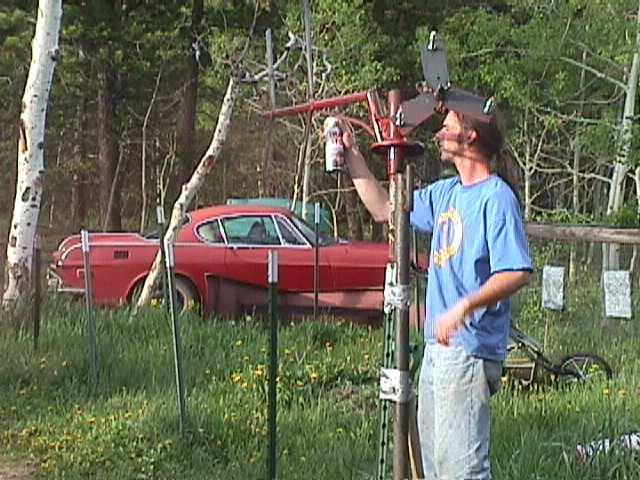
Here the alternator is pretty much done, and the tail is finished! The tail occupies between 5 and 6 feet of area. (If you look real close at the ammeter on the wall, you can see that my last wind turbine is putting out about 40 amps. It was a breezy day!)
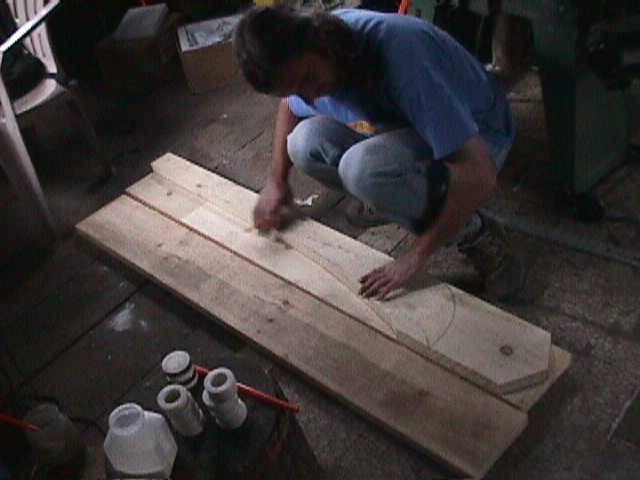
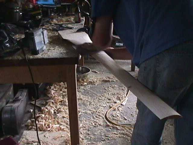
I drew up and cut out the profile for one blade, and Dave is tracing it onto blank boards in preparation for making the other two. The wood here is 6/4 (an inch and a half thick) Eastern White pine, and it's 7.5 inches wide. It's pretty lightweight, but fairly dense and strong. We have a couple knots to work around here, but not too bad.
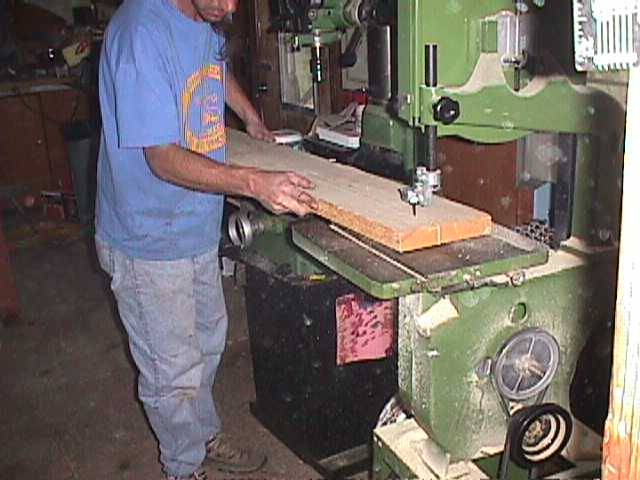
Here Dave is cutting out the blades on the bandsaw.
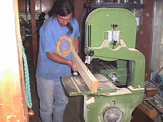
Since the blades get very thin (in this case about 3/8") at the tips, it saves time to remove some of the thickness of the board with the bandsaw.

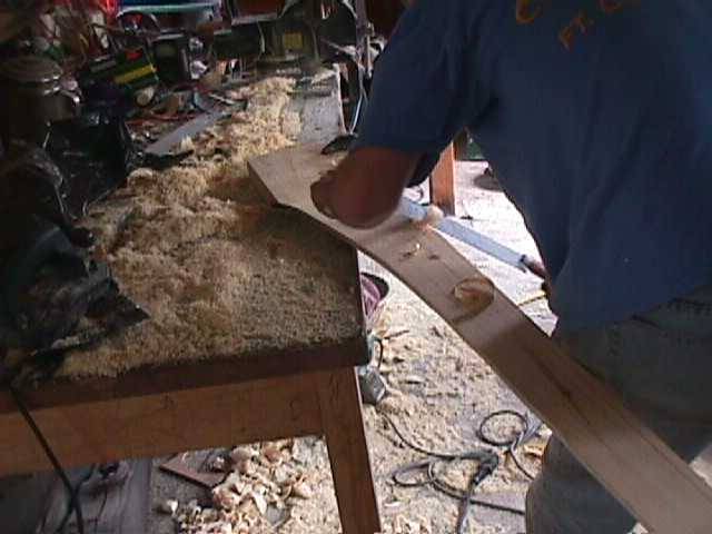
Pictured above we are roughing out the front of the blades with the draw knife.
At the end of the 2nd day we had the front side of the blades roughed out. Each blade is 5 feet long, for a total diameter of 10'. The pitch at the tips is 5 deg, and it gets steeper to about 6 deg in the middle of the blade, at which point it gets steeper quickly towards the root (near the hub) untill we pretty much take up the whole thickness of the board. No real scientific blade design here, just going with what feels good and what's worked fairly well in the past! I've since been advised, and will do this next time - to reduce the pitch at the tips of the blades to something like 2 deg. This would make it a bit faster and a bit quieter.

Here we are finishing up the front of the blades with a power planer. We did most of the work with the draw knife, but the power planer does nicely to finish things up quickly.
While Dave was planing on the blades I made up a cable with lugs on it and wired the alternator in Delta. For more details on Star, or Delta wiring and 3 phase alternators, checkout Ed's 3 phase basics here.
Here we are roughing out the back side of the blade (making an airfoil) with the draw knife.
Same as above, working over the back side of the blades with a draw knife, but here you can really see things coming together! This blade is nearly done.
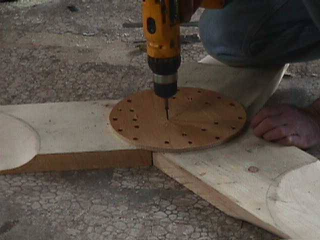
Once the blades were carved and sanded fairly smooth, we put them together - measuring from tip to tip to make sure the distance between tips is equal. Then we used 10 inch diameter plywood disks, one half inch thick, and screwed one on each side of the blades with a ton of wood screws to hold them together.
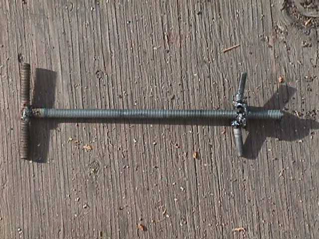
This is a simple tool I made to go with the machine. Notice my beautiful welds... (I have one of those cheap 120 AC mig welders which barely work on good power. Up here I have to run it off my generator which stalls quickly when I start welding. Welding here is very frustrating...)
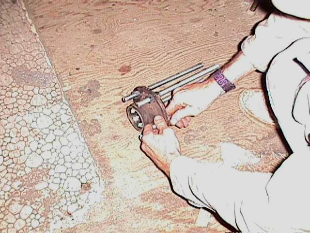
Once you get two magnet rotors like these made up, and close to each other, it become impossible to pull one off without a tool. This makes the job easy. It should also be said... one of these rotors is a very powerful and dangerous thing! Two is twice as bad... anything that gets between them gets smashed. This tool does a nice job of removing the front rotor, but it's not so useful for putting it on gracefully! On this machine we've simply been lining it up and letting it snap into place which works fine as long as you keep your fingers clear! (I did get my thumb in there and my thumbnail was the only casualty. I think I got lucky...) Better would be for me to weld a nut right in the center of the front rotor and then we could use this same setup for smoothly lowering the front magnet rotor onto the alternator.
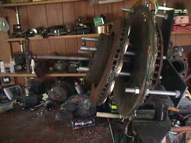
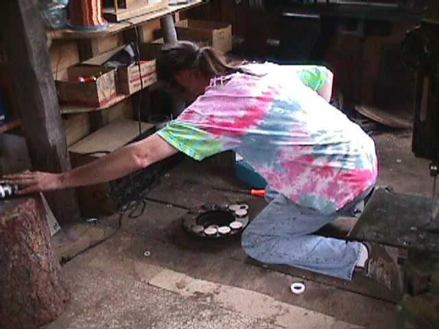
Here is a picture of the wheel puller in action. It doesn't pull it quite straight, but it does a good enough job to make it very easy to pull the rotor off by hand once it's a few inches back.
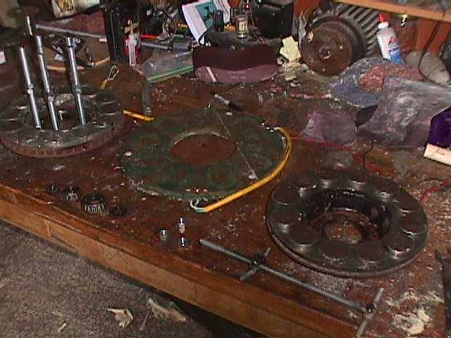
We pulled the whole thing apart in preparation for painting. Here you can see all the alternator parts on my workbench.
Here Dave is putting primer on the machine. First we ground off some of the uglier welds and then cleaned it carefully with gasoline to remove any oil.
Thats pretty much where we wound up at the end of day 3! We used wood stain on the hub and tips of the prop, and on the tail. The rest is good old Avacado green epoxy appliance enamel just like on my last machine. At this point we need to make adjustments in the airgap, get some wobble out of the magnet rotor on the front, balance the blades and test it!
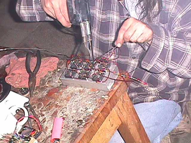
Here Dave is soldering up 6 bridge rectifiers we'll need in order to convert the 3 phase AC current into DC current useful for charging batteries.
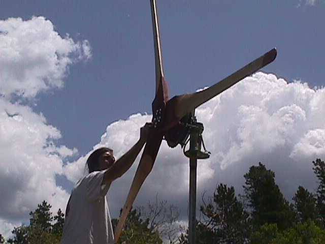
We made a short tower that fits the front of my truck. In the end, this short tower will go on top of Daves (probably wooden) tower down at the caboose. The machine weighs too much to lift it up this high, so we had to disassemble it, and reassemble it on the truck for testing.
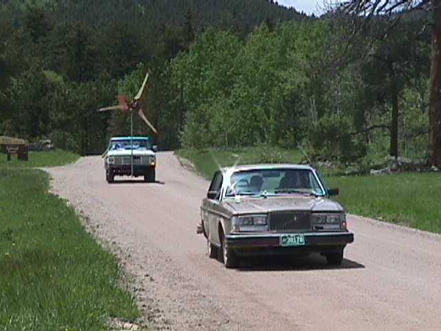
It was a pretty good calm day for this sort of testing today, although the more I do it the more I'm starting to take this sort of data with a "grain of salt". We get pretty consistant readings at higher speeds, but lower speeds (like 10mph) come in all over the place. When testing like this, I have a 12 volt battery on the floor of the truck, a volt meter, a frequency meter, and a DC ammeter. The frequency meter always gives numbers that bounce around and I don't trust it fully, but the numbers did seem to make some sense this time, so I'll write down the rpm as we got it and it may.... or may not be right! This battery was about half charged - and we ran the power to it with about 20' of AWG 14 extension cord (I figured this kind of simulates a longer line from the windmill to the battery made of better wire, plus... it was handy). When we do this, we always run one way down the road at a certain speed, turn around and go the other way at the same speed - so that we can kind of average the numbers out. Even the lightest breeze will cause it to do much better one way than the other.
So here's what we come up with roughly in the truck test...
Our neighbor Tom is in the Volvo pacing us (his speedometer works... mine doesn't) with his flashers on to warn oncoming traffic.
It starts charging at around 110-120 rpm and the frequency meter in the truck was in agreement with the tachometer I used on my workbench.
At 10mph we were getting readings ranging between 5 - 20 amps, 10 amps seemed a pretty good average, so a little over 100 watts. At 10 mph the frequency meter didn't seem to be working so we got no rpm readings. (we later found it a wire had come loose)
At 15 mph it was producing about 15 - 20 amps consistantly both directions. At 20 mph 25-30 amps, and it was just starting to furl. At 20 amps output it seems to be running right around 400 rpm. At 30 amps output it's running right at 500 rpm.
At 25 mph we seemed to be getting around 30 - 35 amps and it was furled out some all the time.
At 30 mph we got consistant readings of 37-40 amps and it was quite furled out by this time (I'd say it was at about 45 deg to the wind). At 37 amps output we recorded around 550 rpm.
I've certainly seen higher numbers from past machines which did not furl before - but I don't think I've ever done so well at very low windspeeds, which is what's important. Output could be increased I think by adding weight to the tail (so it furls a bit later) and making a better stator. I think it's fine as is though. It runs square with the wind - the tail seems of fairly reasonable size and overall it runs pretty well. I like the double rotor design, it's a bit more work than others I've made, but it has 0 load on the bearings, and 0 losses in the laminates. I can give this alternator a good spin by hand, and then walk across my shop and give one of my old laminate alternators a good spin. The old ones will rotate once or twice and then stop... this one will keep turning for 10 or 20 seconds. Time will tell how it holds up! Sure was fun though. We've got 4 days into it now since we started with the front strut assembly off a Volvo and all that's left to do is get it into the air down at the caboose.