| This page is about an older project of ours. We keep ALL of our projects up on the internet for anyone that's interested...but we are no longer pursuing many of these older ideas. Before starting this project, please check our main Wind Power page to check for similar, more recent designs. These will be the top of the list and flagged with an "active project" tag. If you have any questions about what is current and what is not, or why we no longer work on certain designs, first check out our Wind Turbine Evolution page for a detailed history of how our designs have changed over the years. You can also Email us and we'll fill you in as our email volume permits...check the Evolution page first. |
This page is about another homebrew windmill I built using the front strut, hub, bearings, and disk brake assembly from a Volvo 240. The Volvo 240 was built, and sold in large numbers worldwide from 1975 to 1993! There should be lots of cheap parts out there. Surely this design could be adapted to many front strut assemblies. The alternator is very similiar to others and if you look at our other experiments, you'll see many similarities. There are a few points of construction which are not addressed in detail on this page, as many elements of it are redundant. Should anybody want further detail, they should read our other pages about the volvo disk brake alternator, and other alternators we've made.
Para Español, traducción de Julio Andrade.
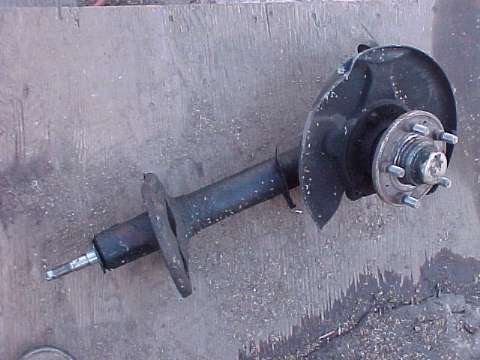
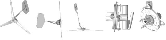
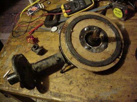
Pictured above is the front strut assembly. The only part not shown in this picture is the brake disk itself, which is necessary to make the armature for the alternator. The strut assembly, in the car, contains the strut (a shock absorber), front wheel bearing, hub, and brake rotor. It serves for the basic frame of a compact, and reasonably powerful wind generator. Once the strut is removed, it leaves a steel tube, which fits over pipe at the top of the tower. The wheel spindle is not at a perfect right angle to the tube in which the strut fit, so the prop will be canted back a few degrees from the mast. This may not be ideal in a windmill... Im not sure really - but I doubt it hurts much, and I suspect that more wind comes "down from the sky" than "up from the ground"! So it may be a good thing. It does allow for the blade to be very close to the pivot at the mast, yet well out of the way from the tower. It's actually such, that with a 7' 6" prop, part of it at the very top runs downwind from the mast! Considering that, and how close the prop is to the mast, the tail can be mounted much closer to the alternator than normal - which allows for a short, and stubby windmill! It's also good that the alternator can be based upon the very strong tapered wheel bearings. I feel confident, that if this assembly is strong enough to support the front wheel of a Volvo, it's more than strong enough for a windmill of this size.
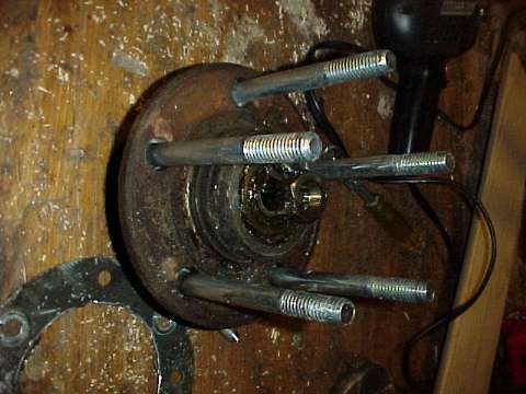
The existing studs are knocked out of the wheel hub with a hammer, and replaced by bolts long enough to accomodate the armature, and the prop. A spacer (not shown) has to be made to hold the brake rotor out. The stator will replace the backing plate, and it is much thicker. The magnets in the rotor will also add thickness, and there will have to be somewhat of an airgap between the stator, and the armature (the brake rotor). The spacer will have to be thick enough to make room for all these things.
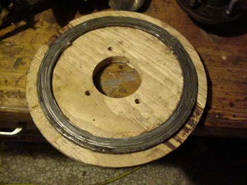
The stator is made up from a disk of 3/4" plywood 11.5" in diameter. In the center of it I cut a hole (3" dia) with a holesaw. This hole will allow room for the wheel hub. The steel laminates lay into a slot which is cut into the plywood 1/4" deep. The slot is a ring, inner diameter is 9.25" and outer diameter is 10.25". The laminates are made up of strips of cold rolled steel sheet metal, they are 1/2" wide, so they stickout of the stator by 1/4". The steel strips are first coated on 1 side with a coat of insulation - I used plastic tape, and then packed tightly into the slotted plywood disk and epoxied tightly. After they are glued in, I apply another coat of epoxy over the top - and especially around the sides. This insures that the coils will not short out to the steel laminates and they will be clamped on very tightly.
Pictured above is the plywood stator bolted on to the strut assembly. It bolts on exactly in place of the backing plate (the sheetmetal plate on cars which covers the backside of the brake rotor), in fact - I left the backing plate in place and put the wooden stator on top of it, because it fit perfectly inside and I figure the backing plate may provide some protection to the wood against weathering. The bolts that used to hold the backing plate on are too short to go through the plywood stator, but I found that the bolts which hold the ball joint to the strut assembly are exactly the right length! So.. if anybody tries this - save those bolts and try to find a strut assembly with the ball joint attached!
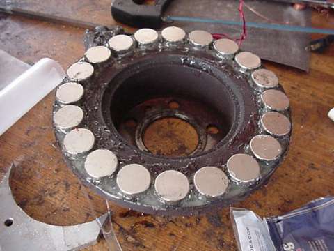
Above you can see the brake rotor with magnets installed. There are 20 magnets in this one, each one is 1.25" diameter X 0.5" thick. Its important that they be perfectly spaced. I cut a shallow slot (about 1/8" thick) in the brake rotor, with inner diameter of exactly 9.25" and outer 10.5" which holds the magnets in place. I spaced the magnets out perfectly, and epoxied them in place. This finished assembly is the "armature".

I made a simple coil winder to make the job easy and the coils consistant in size/shape. It was a quick job to windup 20 coils. Each coil in this alternator has 20 windings of AWG 14 magnet wire. At this point, it should be pointed out that this is a "Single Phase" machine. It could probably be more powerful and offer some advantages if it were wound as 3 phase or even 2 phase - but this gets more complicated and it becomes difficult for me to maintain a thin enough airgap. So far I've had good luck with single phase, and I believe that this alternator will do an adequate job of getting a reasonably amount of power out of the 7'6" diameter prop.

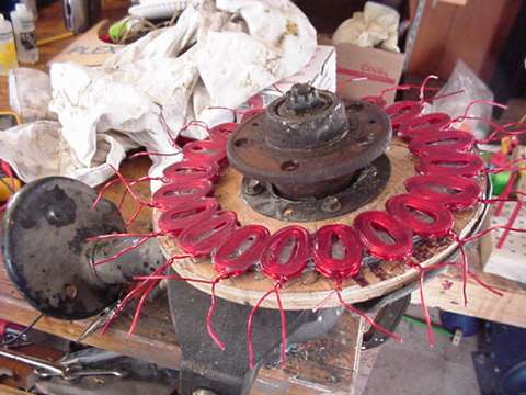
Once all the coils are made, they are laid out over the laminated steel ring on the plywood stator. They must be perfectly spaced around the circle. Once I was sure all 20 coils fit properly, I took them all off and laid a thin coat of epoxy over the steel laminates. I then put the coils back on - and exactly in place, and cover all the coils with a generous coat of epoxy. The assembly then gets covered with wax paper, and I used another disk brake rotor to lay over the wax paper - although anything which is flat, large enough - and none-flexible should work. I put C clamps around and clamped the steel rotor down over the coils. Once all the clamps are reasonably tight, the thickness of the "sandwich" is measured and the clamps adjusted untill the stator is the same thickness all around. This will insure an even airgap when the alternator is complete.
Except for hooking up the coils, the stator is finished in the picture above. The only other thing I did later was coat the entire surface of the wood with epoxy to help the plywood standup against the weather. This is a good time to carefully strip all the wire ends on the coils. As with other machines I've made, it turns out best to divide the stator in half, and hookup 10 coils in series on each half - then, those halves are hooked in parallel. This allows the alternator to reach cut in voltage (12 volts) at around 250 rpm. It would probably be better to use a heavier wire (like AWG 12 maybe) and make each coil only 10 windings, and hook all 20 in parallel, but this works fine.
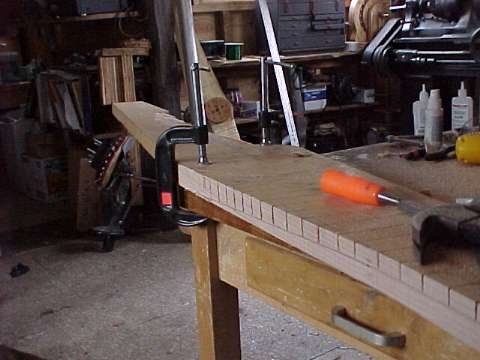
The prop is 7' 6" in diameter, and for simplicity and lack of patience I made it a "2 blader". As it turns out - I've had a few problems getting it balanced well and it does vibrate some when it yaws. I'd have probably saved time in the end to make it a "3 blader". The prop is made from normal - mostly knot free 2" X 10" lumber (1.5" X 9"). At the tips, it's 1/2" thick at the thickest part of the airfoil, and the pitch is 5 degrees. At the hub, its the full 9" wide and the pitch is... as steep as the board will allow! Most of the other props Ive made were made from 1" thick or 3/4" thick lumber and worked reasonably well, however - this is the best one yet, it starts up real easily in the lightest breeze and I believe the extra work involved working the 2" thick boards pays off. Pictured above is the process of chizeling out the board. I first cutout the basic shape of the prop, and then draw lines so I know exactly which material to remove. I can cut down to the lines and the wood chizels out easily and quickly. It took about 4 hours to make this prop and it works great.
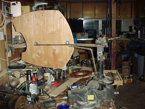
As stated above, using this assembly, with the prop canted back away from the mast - allows for a very short tail! On this the tail is supported by 2 bolts on a small frame I welded up from re-bar. It's very strong. The tail is cutout from 1/2" thick plywood.
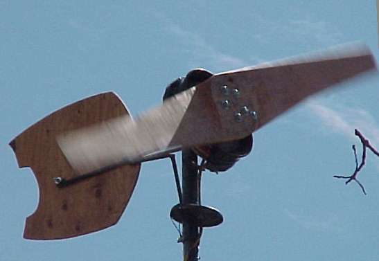
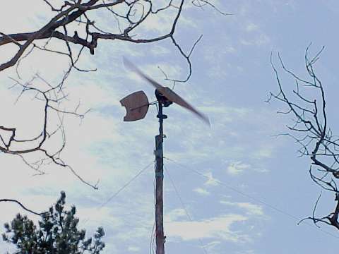
All finished up. The performance of this alternator is very similiar to the other Volvo disk brake alternator shown on this page. In 30mph winds I see about 50 amps, and I have seen over 100 amps in high winds. I like this one best as it was much quicker and simpler to build - the strut assembly provides a good start!. The finished project is an unusually short - and somewhat "cute" windmill! I built this for installation at my own house, and at the time of writing this page it's been up for about 3 weeks. I'm impressed with its performance, and I've seen it survive some incredibly strong windstorms. We live in a gusty... mountain environment - we rarely see sustained, constant strong winds. I've had no problems with needing a furling - or other system of protection to keep these from blowing up in high winds. It seems they can be built strong enough to hold up - and if they dont, they are usually an easy fix. However - in areas which do have high, sustained and constant winds, a furling system of some kind may be needed simply to keep the alternator from overheating! I'm not sure... one day I'll have to stick one of these down on the plains somewhere and see how it holds up!