|
This page is about an older project of ours. We keep ALL of our projects up on the internet for anyone that's interested...but we are no longer pursuing many of these older ideas. Before starting this project, please check our main Wind Power page to check for similar, more recent designs. These will be the top of the list and flagged with an "active project" tag. If you have any questions about what is current and what is not, or why we no longer work on certain designs, first check out our Wind Turbine Evolution page for a detailed history of how our designs have changed over the years. You can also Email us and we'll fill you in as our email volume permits...check the Evolution page first.
|
PAGE 1
Frame fabrication and alternator design procedures
|
PAGE 2
Frame finishing and alternator fabrication
|
PAGE 3
Alternator and blade assembly
|
PAGE 4
Installation on tower and raising!
|
para Español
UPDATE! This has been a good machine and the following pages should be informative, but before you get too involved building this design be sure to see the updated 17 foot design here:https://www.otherpower.com/new17page1.html
And, be sure to check out our book Homebrew Wind Power for more small wind power information!
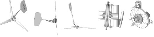
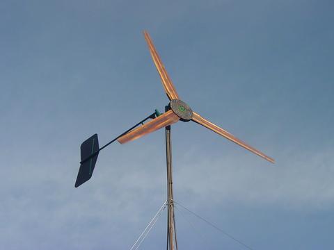
These pages serve as a brief summary about building and flying a 17' diameter wind turbine from scratch. This is very similar to other designs we've built, just scaled up a bit.
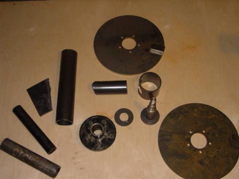
Pictured above are all the metal parts for the machine except for the tail. Unlike most other machines we've built in the past, this one does not make use of any salvaged auto parts. (no Volvo parts here!!) I started with a trailer hub, and spindle. The steel rotors for the alternator are 16" in diameter, cut from 1/2" thick steel. I had this done at a local shop that has a CNC Water Jet cutter. The disks cost around $70 ea, but they came out very nicely - all the holes predrilled etc. The 'yaw bearing' (that part that slips over the top of the tower) is a 16" long piece of 3" diameter pipe. The spindle for the trailer hub is suspended inside a 4" long piece of 4" dia pipe via two steel 'rings' I cut out with hole saws. The steel bracket that supports the tail pivot is frm 1/2" thick steel, it's 6" tall and cut at an angle of 18 deg, very much along the lines of Hugh Piggott's plans - just scaled up a bit.
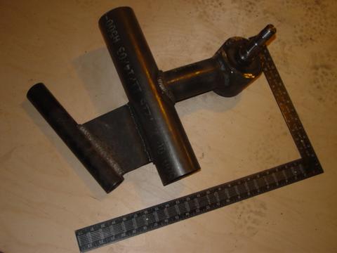
Above we have the main chassis for the machine all welded up. To do it over again, I would probably make a few things stronger. I'd consider a larger diameter yaw bearing. I would reinforce the tail bracket (that flat piece with the 18 deg angle) where it's welded to the yaw bearing. I would use a larger wheel hub/spindle. As it is... it works fine so far, but some minor upgrades would do no harm.

Above I've welded the 6 stator brackets on. The diameter of the stator will be 20", so the diameter of the stator brackets is also 20". I made a simple 'jig' 20" in diameter, and drilled the 6 holes in it - and a center hole that fits over the wheel spindle, (basically a blank stator) and then we bolt the stator brackets to the jig. We can then stick the jig over the wheel spindle and weld the brackets on in exactly the right position.

Pictured above is the template we use to place the magnets on the steel rotors. In this machine we have 16 magnets per rotor. The magnets are quite large - very powerful... and dangerous!! They measure 1.5" X 3" X 3/4" thick.

Here I've laid out the path the magnets will take, and the approximate size that I think the coils should be. Later on, this wooden piece will serve as the bottom of the stator mould so I'll have some guidelines for placing the coils.

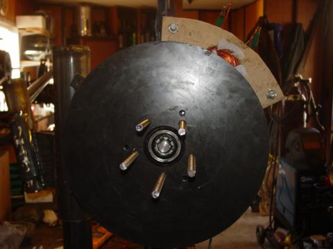
Pictured above we have the magnets 'super glued' onto the rotor, and one rotor is mounted to the machine. Of course we'll need to take this back off so we can cast polyester resin around the magnets.
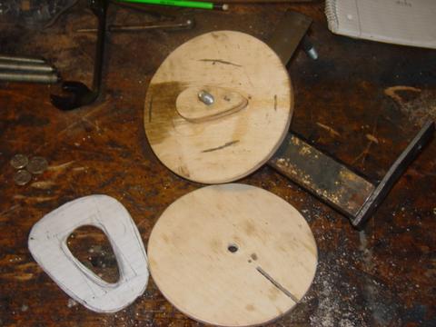
I made the coil winder so that the inside spindle is the size of my 'paper' coil template. The disks are 6" in diameter, the rest is a simple hand crank affair just like all the other wind turbines we've made. Most past machines had slightly thinner (1/2" thick) magnets. This machine is using thicker 3/4" thick magnets, so we can also run with a slightly thicker stator. This stator will be 5/8" thick, so the coils can be a bit thicker. The coil winder, when assembled - makes coils 9/16" thick, I like to wind them a bit thinner than the stator.
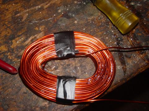
First we wind 1 test coil. Since this is a new design - I needed to make a test coil of the 'right size'. Then I can run that between the magnet rotors and get an idea of how many windings we need for a desired cut-in speed. Since this is planned to be a 17' machine, we want a cut-in speed around 70 - 80 rpm. This test coil consists of 79 turns of #13 wire.
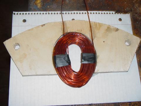
It would've been prettier if I'd cast this coil into such an assembly, but I tend to get impatient sometimes. We cut out a piece of plywood and glued the coil in there so we could mount the coil on 2 of the stator brackets and run it between the magnet rotors.
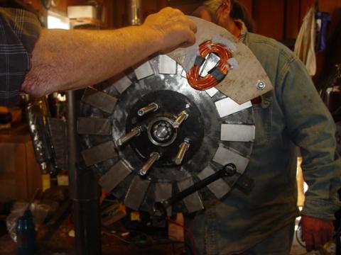
Here we're testing the coil with only 1 rotor on the machine. We have an optical tachometer to measure RPM accurately. Here we see 2.4 Volts @ 70 rpm. At this point it should be noted... these magnets are really crowded on the disks! At the inner diameter of the 'magnet ring' there is less than 3/8" between the magnets. This surely causes some cancellation in the coils when we have two opposite poles over 1 coil leg at the same time, and it results in some flux going straight from magnet to magnet, rather than through our coils where we want it. So we are not making the very best use of our magnets on this machine, but... we are keeping it perhaps a bit smaller and lighter weight by doing things this way. It is a compromise.. we spend a bit more on magnets, and we have a slightly lighter weight, smaller machine.
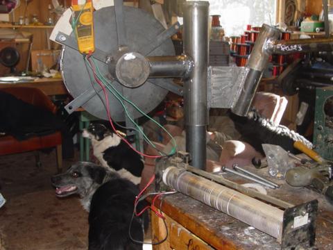
Pictured above is the back of the machine with the test coil mounted. You can also see the large resistor I used to 'load up' this test coil and get a rough idea of what sort of power to expect at a given rpm.
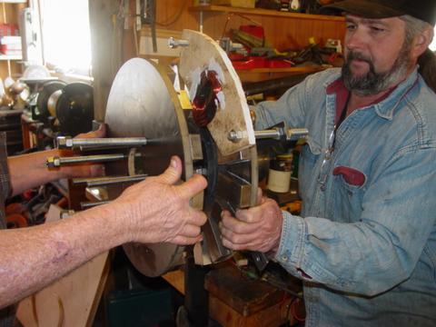
The attraction between these magnet rotors is very strong and very dangerous!! We drilled at tapped 3 holes in the front rotor so that we 'jack' the rotor down , or 'jack' it back up with 3 1/2" pieces of allthread. (jacking screws) It takes a while, but it's the only safe way to do this.
Editor's note -- George's fingers are in a BAD place. If the jacking screws were to fail, he would LOSE 4 fingers. This is unlikely--but it's always something to keep in mind when dealing with any magnet rotor.
There we have the front rotor on. At 70 rpm now, with this one coil, we see 5.4 Volts AC - which, is just about perfect for 48 volt cut-in. So my test coil is right in there. I prefer a slightly higher cut-in speed, so the actual coils will have a few less windings of slightly heavier wire. One other test I did... I wired this single coil up to a big resistor (somewhere around 1 ohm I think) and cranked it hard by hand. At about 104 rpm, under load, I had 6 Volts AC and 6 Amps into the resistor (36 Watts). Im not sure if I'm figuring all this right - but I think that with 12 coils wired in 3 phase Star configuration... I should be close to 400 watts @ 100 rpm.
At this point we have about 2 days work into the project.
PAGE 1
Frame fabrication and alternator design procedures
|
PAGE 2
Frame finishing and alternator fabrication
|
PAGE 3
Alternator and blade assembly
|
PAGE 4
Installation on tower and raising!
|