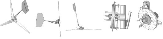
The completed unit. It's already been attached to a homebrew wind generator with an 8-foot diameter, 3-bladed rotor--and is up and flying! See it HERE! We've already seen peaks of over 60 amps into a 12 volt battery bank, and it survived 60-mph winds last week. Steady output of 30 amps in 28 mph winds, and reaches charging voltage at around 12 mph.
After building a couple of reasonably successful alternators out of wood, I thought it would be fun to make one utilizing steel behind the magnets, and some sort of steel laminates. The most recent wooden alternator I built works great, but the lack of iron behind the magnets and coils severely limits its maximum output and may cause inefficiencies, especially at higher output levels. Iron behind the magnets nearly doubles the magnetic field density through the coils. Putting steel laminates behind the coils has the same effect, again nearly doubling the field density through the coils. The wooden pillow blocks and ball bearings in the wooden alternator also limit its strength and durability. This alternator uses a rock-solid Volvo wheel bearing, which is built to take thrust forces and abuse, and will hold up well to weather.
Parts/supplies required to build this alternator
Front wheel assembly from Volvo 122s, incuding wheel spindle, wheel hub, bearings, and brake disc.
3 square feet of 1/2" thick plywood
5 pounds AWG 16 Magnet wire
18 NdFeB disc magnets, 1.5" diameter X 3/16" thick
1.5" drywall screws
Epoxy (lots of it!)
A bunch of steel banding material for the laminates (I used bandsaw blades!)
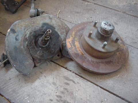
This alternator is built around the front wheel/disk brake assembly from an old Volvo 122s. I chose the Volvo parts simply because I had them on hand; this concept could easily be adapted to any front disk brake assembly. Odds are, another type might even work out better. The main advantages to using the front wheel hub and brake disk disc from a vehicle are: 1) Very strong bearings - the front wheel bearings are tapered bearings, they hold up well to thrust. 2) A nice steel disc to put the magnets on! 3) Cost, and time saved. Building this from scratch would be fairly expensive and involve a fair amount of machine work. Here, in one cheap package from almost any junkyard many of the problems are solved.
This is the only machine work involved, very easily done by any automotive machine shop, or anybody with a metal lathe. I cut a slot 1.5" wide in the back of the brake disk very near the outer edge. (I left about 1/16" steel on the outer edge) This slot serves to hold the magnets in. It might not be needed, but at high rpm there is risk of the magnets flying off. This slot should hold them in tightly.
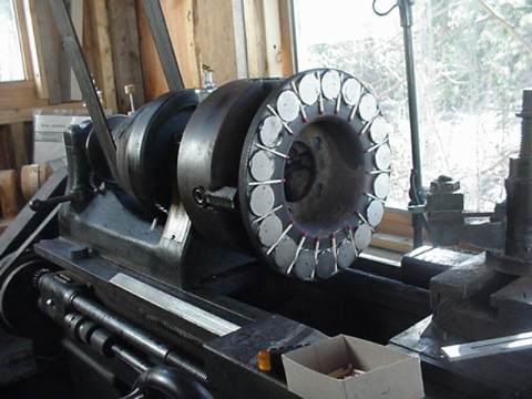
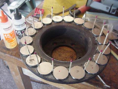
The magnets are N40 grade NdFeB rare earth magnets (available from our shopping cart). In this alternator, I installed 18 magnets. I put them all together side by side, and measured the gap. I then divided the gap and it turned out that there should be exactly 0.08" gap between each magnet. Wooden kitchen matches fit the bill, so I spaced the magnets evenly using kitchen matches! At a later time, after the magnets and brake disk are cleaned carefully, the magnets are epoxied down in the slot, and the kitchen matches removed. One safety note: At this point we have 18 VERY powerful magnets stuck down to a perfectly flat surface, making for one heck of a strong magnetic assembly! Should this get stuck to another flat, steel surface, it could be IMPOSSIBLE to remove! If your fingers get stuck between the armature and another metal surface it would probably SQUEEZE them right off - so be careful if you try to build this, and keep it in a safe place!
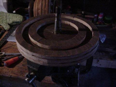
Pictured above is the beginning of the plywood stator. It is made out of laminated plywood discs. The total thickness is 1.5". The top layer, which is 1/2" thick, has a slot 1" wide at about 10" diameter so that steel laminates can be epoxied in. Over that will be the coils. (you'll see this later in the page!)
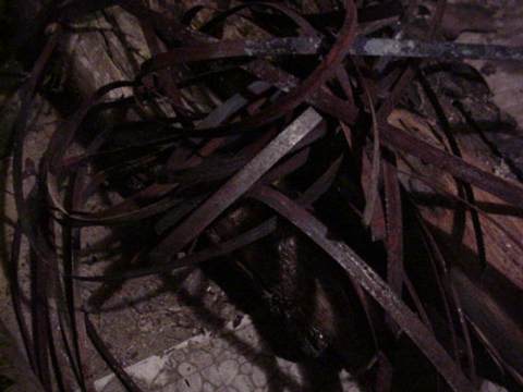
I made the "steel laminates" from old rusty 1/2" bandsaw blade. The reason for thin pieces of steel (laminates) is to prevent the low voltage, high amperage eddy currents which would be very problematic with a solid steel core. I annealed the bandsaw blade in a wood stove, hoping to make it more flexible and a better magnetic conductor. My thought was that coiling it up and sticking it into the stator (in the slot described above) would serve as a good magnetic conductor so the field density through the stator coils would be maximized. In retrospect, bandsaw blade is NOT the best choice. Although the alternator works well, the bandsaw blade I used is a reletively high carbon steel, and makes for a pretty good permanant magnet! So - although eddy currents are not a problem, the Neodymium magnets in the armature actually magnetize the metal, creating a noticable drag on the machine. It's call "hysteresis," and it's definitely something to avoid in the steel laminates of an alternator. Anyhow...in tests, even after I built a complete windmill from this alternator, it still starts up reasonably well and produces plenty of power, so this setup, although not ideal, still works fine. In the future, I will find better metal to use than bandsaw blade. The main point here is that coiling up thin strips of metal behind the coils makes for a simple solution to the problem of having steel laminates behind the stator coils.
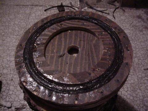
Pictured above you can see the plywood stator, with the steel "laminates" (strips of bandsaw blade) glued into the slot. Each layer of metal should be insulated from the ones next to it in order to preven eddy currents. Eddy currents in a steel core are very low voltage, high current in nature. With that in mind, I assumed that simply the corrosion on the bandsaw blade and the epoxy resin which I used to glue them in would provide good enough insulation. I believe it did - however, it would be "safer" to actually put a thin paper insulating material such as masking tape between each layer of metal banding to ensure that significant eddy currents do not develop.
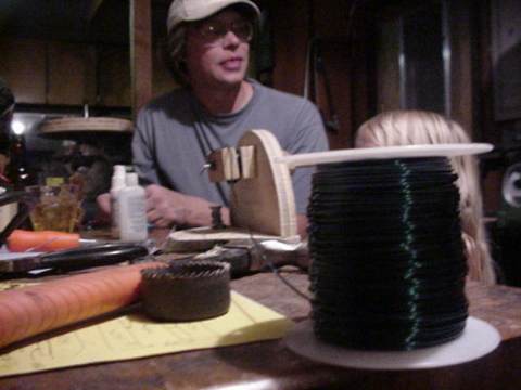
Above is pictured Ward (my neighbor who we are building this machine for) winding coils on the same coil winder I made for the wooden alternator. Each coil in this machine is 30 windings of AWG 16 magnet wire. The coil winder we used probably wound the coils a little taller than needed, so the unit could be improved by making the coils a little smaller. (In other words, these coils came out about 1.5" wide, and 2.5" tall - there would be less resistance in the stator if the coils were only 2" tall and some wire could have been saved) After each coil is wound, it is carefully set aside to be glued and clamped over the top of the stator at a later time.
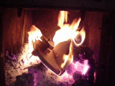
Ward works well with his hands, but....the coil winder I made was quickly built, for a different machine and really only meant to be used once. He got a bit impatient with constantly gluing it back together, and its rather crude performance. After winding the last coil he threw it in the stove, so - our next alternator is bound to turn out a little better and we should get through the coil winding phase with hopefully a little more patience left over!
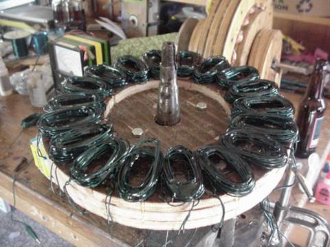
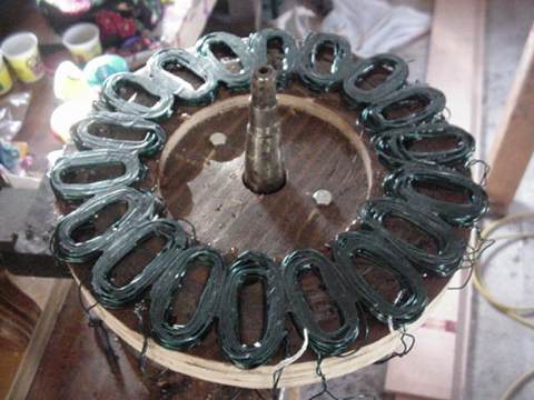
As I stated above, the coils come off the winder in rather delicate condition, and rough in appearance. The next step is to line them up around the stator and put them in exactly the right place. Since there are 18 coils, each one must occupy a 20 degree arc around the stator. This is actually easily estimated by first perfectly aligning the magnets around the armature (the brake disk), placing all the coils down around the stator (pictured above), and then placing the brake disc down over the stator, making sure that there is 1 coil located exactly under each magnet. Sometimes it was necessary to squeeze the coils by hand so that they would fit in the space provided. Once everything is lined up properly, I "tacked" the coils down with super glue so they would stay in their places.
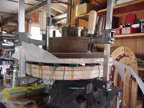
Once the coils are tacked in place, I generously covered them with epoxy and layed wax paper over the top. I took a 12" diameter disc of plywood, and layed that over the wax paper. Then I took the brake disk (which is 11" diameter), centered over the stator, and clamped the whole thing together tightly. It is very important! When clamped, the thickness of all the coils around the stator should be the same. Otherwise, when completed the gap between magnets and coil will be wider in one part of the alternator than another. So, when one side had thicker coils than another, I would simply adjust the clamps until it was about even all around. As it turned out, I somehow missed and one side of this alternator does have coils about 1/8" thicker than another side...but it works fine anyhow!
While I had the glue out, I glued the magnets into the brake disk at the same time. Once the glue set up partially, I removed the matchstick spacers.
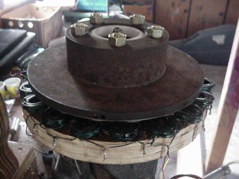
Above is pictured the stator, mostly complete, with the coils smashed down tightly and glued well. At this point, I coated the assembly (plywood front and back) with epoxy to weather proof it as best I could. I divided the coils in half, hooking 2 sets of 9 coils together in series and figured I would decide later whether to hook the two halves in series or parallel - this was not decided untill a prop was made and I actually got to test it in known windspeeds.
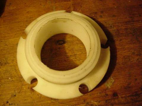
When originally used on the car the wheel hub was in direct contact with the brake disk, which allowed for the brake disk to fit well with the brake caliper and the backing plate. In this application, the backing plate is replaced by the stator, which is about 2" thick when you account for the thickness of the wood plus the coils! So I had to make a spacer which would allow for the brake disk to sit about 2 1/2" out away from the wheel hub in order to allow space for the wooden stator. Pictured above is that spacer, which I made out of some kind of white plastic that I had on hand (maybe Nylon but I'm not sure). In a bind, it could probably be made from wood - a hard wood like Maple or Oak would probably be fine. A machinist with lots of goodies on hand and a lathe could make it real nicely from Aluminium. If that is not available, it could be made from wood with a bandsaw and a drill press.
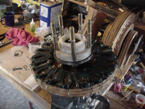
Pictured above, all the parts are assembled except for the armature. Note the long bolts sticking through the hub and spacer. These will hold the rotor on, and the armature will not be held down tightly until the rotor is tightened. Although other systems might work, in this case I decided to lightly tack weld the bolt heads to the wheel hub on the bottom, since it would be impossible to hold them with a wrench once the brake disk (armature) was installed.
So thats it, all finished up! At this point it becomes obvious that it will be an effective low rpm alternator. There is slight drag from the hysteresis problem of magnetizing the steel bandsaw blade as described above, but it isn't too bad. It spins fairly freely, and when the leads of the stator are shorted out it locks up and becomes very difficult to turn. When the stator is hooked up with all 18 coils in series, it is easy to spin it up to about 15 volts by hand. Next step is to chuck it in my lathe and get some real test results.
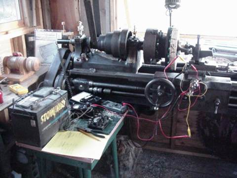
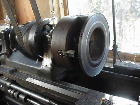
Pictured above is the "test rig." It's somewhat limited by the motor on my lathe - the max speed I could test it at was 500 rpm, and even at that speed it loads up the motor and slows it down. The problem is that my lathe only has a 1/2 hp motor on it. The reason for this is that I run my whole shop off my batteries and a "cheap Chinese" inverter! Someday I'll upgrade to a 1 hp motor, which my inverter should barely run...but for now my tests are limited.
I have an accurate tachometer (a DC generator hooked to a well-calibrated meter), a voltmeter, an ammeter, and a 12 volt battery for performing reasonably accurate tests.
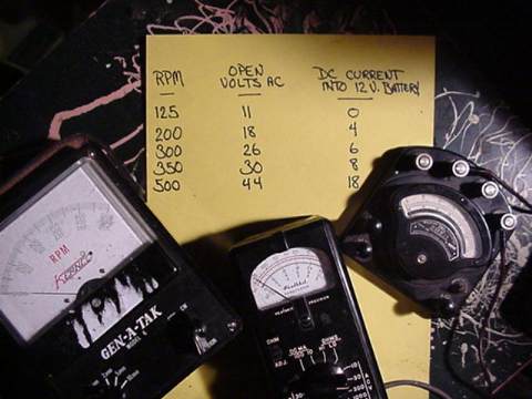
Above are pictured the results. For this test, all 18 coils in the stator are hooked into series. It appears that the numbers (amps into the battery) are climbing quickly above 300 rpm, but unfortunately I could not make tests above 500. As shown in the picture, open circuit voltage is about 1 volt per 12 rpm. Shortly after making these tests, we built the windmill and put it on a "test mast" which was bolted to the front of my truck. In testing it became clear that the unit (with all coils hooked in series) became inefficient above about 30 amps (into a 12 volt battery), so we divided the stator into two sets of 9 coils in series, and wired the two sets of 9 in parallel. In this configuration, we lost very little at low windspeeds (it still put out power at 10 mph!) but saw 60 amps (about 700 watts) into the 12 volt battery at 40 mph. More information about these tests will soon be available on the follow-up webpage about the windmill we made from it!
In conclusion, I think this is a great way to make an alternator. Keep in mind that I put this together as I went, without a plan! Several improvements could be made. As tested, the average gap between coils and magnets in around 1/4"! With better core material and careful attention payed to the thickness of the coils, this gap could be reduced for improved output. Overall it's dirt simple, super strong and the output seems reasonable. The bearings in the Volvo wheel hub are huge, and should last practically forever. The cost? The magnets would run about $100, the wire about $40, the glue about $15, and hopefully a wheel assembly could be had for next to nothing. It's not a bad price for an effective alternator probably capable of 1000 watts. Again, in the future I would NOT use bandsaw blade. The best bet would be to find the very same metal used in motor laminates, although I have a feeling that hot rolled sheet metal is not a bad way to go. There's a good chance that the steel strapping material used to hold stuff down to pallets would also work fine. Overall, it's a good way to build a tough, useful alternator with minimal tools and highly available materials.
I owe some thanks here for the ideas involved!
Be sure to check out Hugh Piggott's site. His brake drum windmill inspired me to consider making use of available auto parts. His design is well proven, and probably the most popular "home brew" windmill plan available at this time. Hundreds have been built. He has recently been building a different sort of "radial" alternator - visit his page to check that out!
Dragon'sWind Stuff Now page has a very similiar 3 phase radial alternator, with details about the construction. His page is full of useful formulas, products and information, and his correspondance with me has been helpful and inspiring! Be sure to check it out!