
We get a lot of email from people who are on the power grid who have great interest in building something like this to 'save on utility bills'. We have had a couple of these machines grid tied with good results, but... keep in mind the payback period is likely to be quite a while, or, possibly never depending on how well you take care of your batteries. Batteries are expensive! This machine is specifically designed for battery charging and it's probably quite useful and cost effective for people who already have 24, or 48V renewable energy systems in place.

Pictured above are most of the metal parts with the exception of the tail boom, tail vane bracket and the piece of pipe that fits between the yaw bearing, and the alternator head. This page is not meant to serve as plans, but more of a diary - with some specific details about how we build this machine. You should read our book "Homebrew Wind Power" for more details. Between that page, and this one - you should be able to put most of it together. If you have questions we're happy to take your email.
2 - Wheel Hub. This is a wheel hub for a trailer, I believe it's designed for a 6000 pound axle. I get these from South West Wheel company. It comes with bearings and its a #42 spindle which is available from the same company. This hub fits between the magnet rotors. The back rotor fits right up against the back of the hub and often times we have to turn the back of the hub slightly on a lathe so that the rotor will come flush to the back of the wheel hub.
3 - Spindle housing. This is the bit that the stator bracket is welded to - it supports the spindle in its center. Its 5 inch diameter sched. 40 pipe, 5.75 inches long.
4 - Stator bracket. It has 6 'arms' which support the stator. It's cut from 1/4 inch thick steel. The hole in the center is 2.25 inches in diameter. The holes at the end are 5/8 inch in diameter (to allow for the 5/8 inch all thread studs we use to hold the stator on with)
5 - Yaw Bearing. The yaw bearing is the pipe that fits over the tower stub. It's 4 inch diameter pipe, 30 inches long.
6 - Magnet Rotors. They're cut from 1/2 inch thick steel and they're 18 inches in diameter. We put 6 holes (for cooling, and front rotor adjustment) around the center. They're 1.75 inches in diameter evenly spaced around a 4 inch radius. Of course we also have 6 holes for the studs 5/8 inch in diameter and 6 holes in the front rotor to be tapped 1/2-13 tpi for jacking screws.
7 - Spindle. It's a standard #42 spindle that fits the hub - we get that from South West Wheel company.
8 - Yaw Bearing Cap. It's cut from 1/4 inch steel and fits in the top of the yaw bearing. It's 4 inches outer diameter and 1.25 inches inner diameter. The 4" diameter fits inside the top of the yaw bearing, the 1.25 inch hole in the center is for the line (wires from the alternator) to pass through into the tower.
9 - Rear spindle support. This is the part that fits in the back of the Spindle Housing (part #3). It's 6 inches outer diameter (to fit inside the 6 inch pipe that the spindle housing is made from) and has a hole 2.25 inches diameter (so the spindle fits into it)
10 - Tail Pivot. It's 24 inches long made from 2 inch pipe.
11 - Tail Bearing. This is the part to which the tail boom is welded and it rotates on the tail pivot as the machine furls. It has a notch cut out which is 9 inches long (from the bottom) and about half the pipe (180 deg of the pipe is cut out) - a bit less is OK or even better, it's not critical.
12 - This is the 'scrap' from cutting out the notch for the tail bearing. We'll weld this back to the tail bearing to strengthen it.
13 - Blade Hubs. Overall they're 28 inches in diameter with 3 spars, 10 inches wide. We won't go into detail here. Obviously they need to have the 6 holes for the studs on a 5.5 inch circle to accomodate the studs. Then we have 5 more holes (5/8 inch diameter) for bolts to go through the blades. All these holes are 5/8 inch diameter. The rear blade hub has a 3 inch diameter hole in its center so that the grease cap on the hub can fit into it.
Again, missing from the picture above: the tail boom, 1.5 inch pipe and 8 foot 6 inches long. The tail vane bracket (helps support the tail vane) is 1.5 inch x 1/4 inch bar stock, 4 feet long. We also put a gusset beneath the tail boom (it's welded on one end to the tail bearing and on the other end to the tail boom) and it's usually about 70 inches long. There are a couple of smaller gussets between that gusset and the tail boom to make things more rigid. We call those 'tail boom gusset gussets.' Another part not shown is the tail bracket. It's the part that fits between the yaw bearing and the tail pivot. It's another triangular part cut from 1/2 inch thick steel. It's 9 inches long, one inch wide at the bottom and cut at 20 degrees. The next picture will hopefully clarify that a bit.

Pictured above is the previously mentioned tail bracket being setup for welding to the tail pivot. To get things nicely centered we mill a 3/8 inch slot into a piece of angle iron so that we're sure to get it perfectly centered and aligned with the pipe that is the tail pivot.

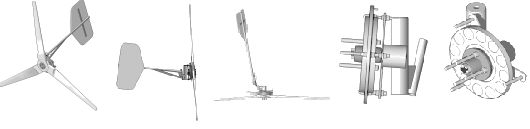
The picture above shows the whole alternator head pretty much finished. You can see how the stator bracket gussets, stator bracket, spindle housing and rear spindle support go together. We also cut a 4.5 inch diameter hole (slightly oval shaped) into the spindle housing (that piece of 5 inch diameter pipe) to accommodate a short piece of 4 inch pipe which will connect this whole assembly to the yaw bearing.

The alternator head jigged up to weld to the yaw bearing. The above mentioned 4 inch pipe is overall 6 inches long so that the alternator spindle is off set from the center of the yaw bearing (and the tower) by 8.5 inches. Look again at the 10 foot wind turbine plans to see how we do this without a jig. In the picture above we are using a jig we made - it makes life easier if you're making more than one machine but it's not necessary.

Pictured above all the metal work for a 17 foot wind turbine is finished. At this point we take down (I say down... because we're 40 miles from, and 3500 feet above TOWN and they do all the powder coating in town) all the parts, including the magnet rotors and the blade hubs and have them powder coated.

Powder coat is nice, very durable and for the price of getting it done I could hardly justify the expense of good automotive paint and my time spraying it on. We powder coat all our stuff these days.

There's a picture of the same machine from the front. Now we can move on to other parts of the project.