| This page is about an older project of ours. We keep ALL of our projects up on the internet for anyone that's interested...but we are no longer pursuing many of these older ideas. Before starting this project, please check our main Wind Power page to check for similar, more recent designs. These will be the top of the list and flagged with an "active project" tag. If you have any questions about what is current and what is not, or why we no longer work on certain designs, first check out our Wind Turbine Evolution page for a detailed history of how our designs have changed over the years. You can also Email us and we'll fill you in as our email volume permits...check the Evolution page first. |
| PAGE 1 | PAGE 2 | PAGE 3 |
Para Español, traducción de Julio Andrade. Po polsku -- tłumaczenie Leszek Markiewicz
These pages are HUGE with lots of photos to download, so please be patient...it may take some time. All of the diagrams drawn with DanCAD are scanned larger than they appear on these pages. Sometimes they don't show very clearly, depending on your screen size. If you have trouble reading a diagram -- first try Right Click --> View Image to enlarge it. You can also do Right Click --> Save Image or Right Click --> Print Image to get the hi-res version.
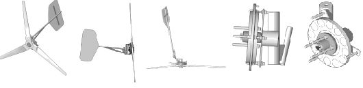
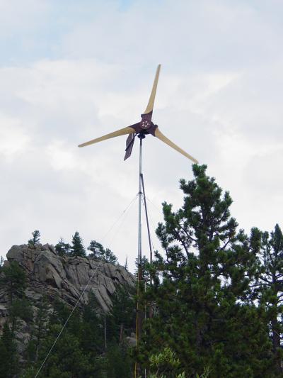
This is a sort of diary about how we built the last 5 windturbines, all of which are pretty much identical. The windmills use axial field, dual rotor alternators, with a furling tail system and a 10 foot diameter 3 blade prop. It's very much inspired and along the lines of Hugh Piggott's latest design. Click Here to visit his site for lots of useful information.
The windturbine I'm describing here turns very freely and should start generating power at, or below 7mph. Click here to see a less detailed page about a nearly identical machine I helped a neighbor build earlier in the summer. They spin easily, they start charging in low winds, and seem to work pretty well. They are quiet, slow.. and seem safe and strong. Time will tell, this is an experiment!
Here is a fairly complete list of the materials we used, not including the tower.
80" of 1/2 - 13 allthread
10" of 1/4 - 20 allthread
44 1/2 - 13 nuts
2 1/4 - 20 nuts
1 washer 2" outer dia and 1/2" inner dia
6' of 3/4" steel pipe
6.5" of 1" steel pipe
2' of 2" X 3/16" steel bar stock
3 or 4' of 1" X 1/8" steel bar stock
A half of 1/2" plywood
about 6 square feet of 3/8" plywood
18" square piece of 3/4" plywood
A little bit of 1/4" masonite and misc lumber scraps for the coil winder
A quart of polyester resin and some fiberglass fabric
A bottle of baby (talcum) powder
thin viscosity superglue and accellerator for hardening coils
5 pounds of AWG 14 magnet wire
24 NdFeB magnets 2" diameter X 1/2" thick
strut tube/wheel spindle assembly from a volvo 240
2 11" diameter brake rotors from a volvo 740 or 850
3 boards, 5' long and at least 1.5" thick and 7.5" wide
lots of 1.5" long wood screws, at least 60
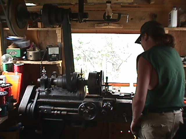
And for tools, I used common hand tools and power tools. A metal lathe is nice for this - there are a couple quick simple things that can't be done easily without it. The lathe work is easy and any machine shop could do it quickly and cheaply for you. A bit of redesigning and one could live without it. I had a welder, a drill press, belt sander, power planer.. the usual! A draw knife is a MUST HAVE for carving the prop. I'd not try this project without a reasonable workspace and plenty of tools. For me, it takes about 30 hours to build one - I don't fret too much about little details or getting things just perfect.
The most expensive part of the project is the magnets, they cost around $250. The rest of the cost depends on what gets purchased new, what gets salvaged, and resources on hand. I like to use salvaged, or recycled materials whenever possible. I'd figure the cost of the whole system not including batteries or a tower to be around $300-$400. In the end we get a machine which performs quite well, especially in low windspeeds. I think one would be lucky to get similar performance from a commercial machine costing less than $1500. I think it's a great way to go so long as the recources are on hand and so long as it's fun! In the end there is a wind turbine which the builder understands, and feels comfortable maintaining, modifying, and repairing.
This page will often have pictures of different machines in progress. When we built these, I had 2 neighbors come by and we worked together on 3 machines at one time to make things a bit more efficient and fun!
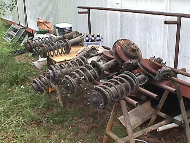
Pictured above are the Volvo 240 strut assemblies we start with. Volvo made the 240 for almost 20 years! They should be easy to find. We have to remove any extra parts that come with the strut assembly.
We'll need to remove the strut inside (shock absorber), any brake parts, and the spring. One should probably either pay a shop to remove the spring, or get a spring compressor. These springs are under quite a bit of tension in this assembly. Simply loosening the large nut which holds all this together will result in the spring popping off with quite a lot of force! I've seen them fly over 20', if you are not very careful this could be quite dangerous. We'll take the wheel hub off, remove the bearings - clean and re-grease them. The Volvos are nice, they have very nice large wheel bearings which may never wear out in this application. Compared to banging your Volvo up and down the road, these bearings don't see much stress in a wind turbine application.
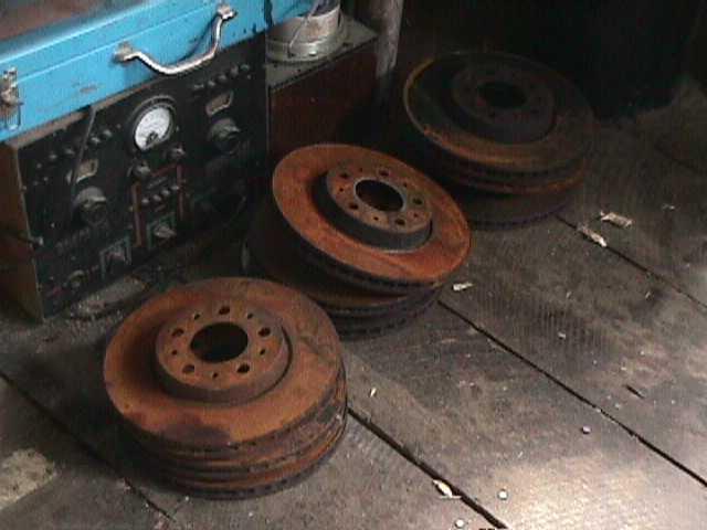
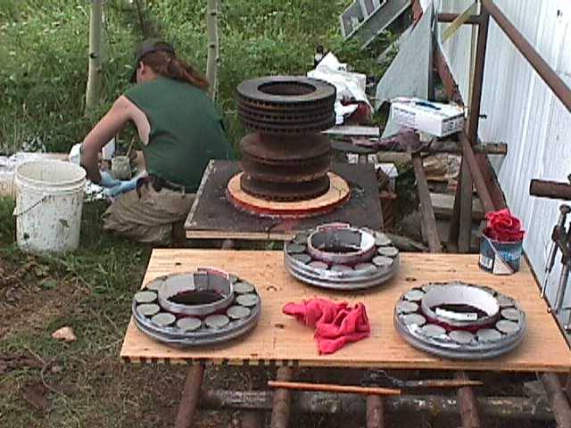
The Volvo 240 comes with 10" diameter brake rotors. I prefer a bit more diameter for a machine this large, so I found larger rotors on some of the newer Volvos - and they fit the same bolt pattern. Brake rotors on modern cars get thrown away frequently. Our local Volvo shop always has a dumpster full of them! Each machine requires 2 11" diameter brake rotors, these will be the "armature" for the alternator. Each rotor will have 12 magnets fixed to it.
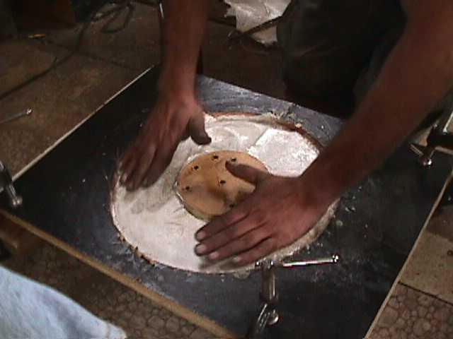
I like to turn down the inside of the brake rotors just a bit. This leaves a rougher, yet flat surface for gluing the magnets down. We also leave a very thin lip on the very outer edge of the rotor to help with placing the magnets in a concentric circle - and to help hold the magents in against the centrifugal force they'll see when the alternator is turning quickly. This is an easy operation- if I didn't have a lathe I think any automotive machine shop could do it quickly.
The other important operation with the lathe, is to bore the hole in the middle of 1 brake rotor a bit larger so that it can fit over the back side of the wheel hub. The picture below will hopefully show that.
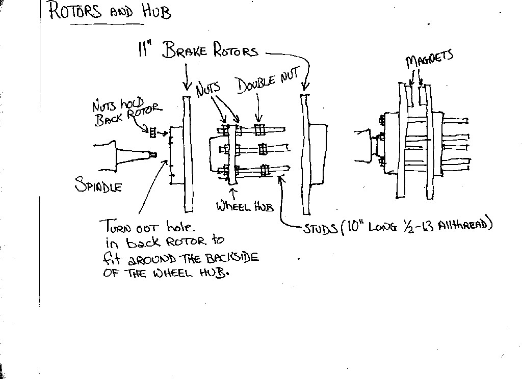
The picture above shows how 5 long studs, made from the 1/2" - 13 allthread will hold all this together. The coils will exist between the two brake rotors, in between the magnets. These brake rotors were designed to fit over the front of the wheel hub, and the hole in the middle is not quite large enough to fit over the backside of it, so this is why we need to turn it out just a bit with the lathe. I suppose this could be done with a grinder or something...
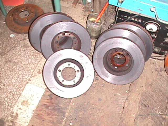
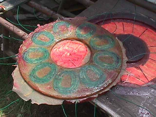
Above is shown the brake rotors after being turned. You can see that the hole in the ones on the left is slightly larger than those on the right. After machining them, we clean them carefully with paint thinner or gasoline so that we can glue the magnets on later.
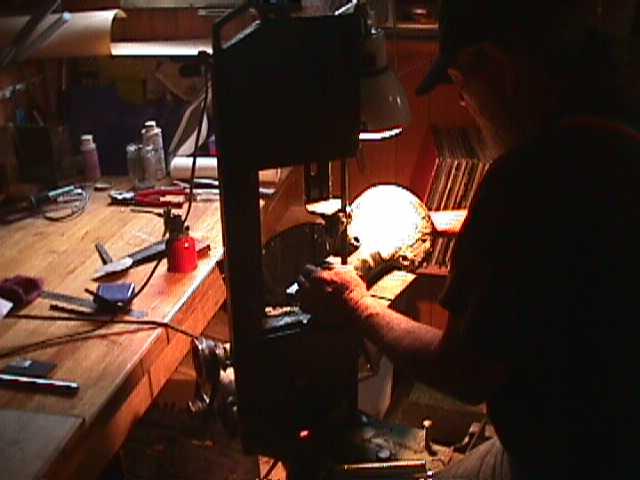
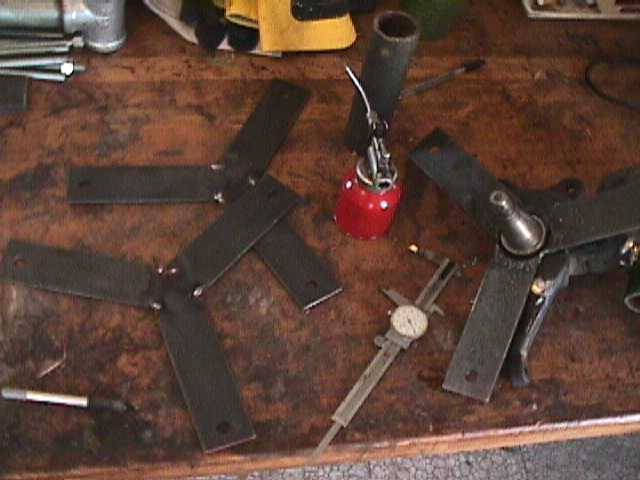
Tom is cutting pieces on the saw. It's nice to get a list of all the parts you need to cut and get it over with in one shot. Here Tom is cutting a 5' piece of 3/4" pipe, 5 pieces of 1/2"-13 allthread 10" long, 3 pieces of 1/2"-13allthread 6" long, 1 piece of 3/4" pipe about 6" long, and 1 piece of 1" pipe about 6.5" long. We also need 3 pieces of 2" barstock cut at 7" long, with a 120 deg angle on one end. These are for the bracket which will hold the stator in place. A picture of that is below. It's important to be careful and try to leave nice edges when cutting allthread, either with a bandsaw or a hacksaw! It saves time... cleaning all these ends up with a grinder so the nuts will thread on is tedious and completely unnecessary if you make careful and clean cuts.
Pictured above are some of those pieces I described above.

Above we can see the strut assembly mostly stripped of it's extra parts. The picture below will show how we need to cut this up and weld it back together to make the furling system work.
In the older and simpler wind turbines I made there was no system by which the machine could turn away from high winds. In this one there is, and part of that simple system requires that the alternator be offset to the side of the tower a bit. So we need to cut up the strut tube! I used a bandsaw, it could be done with a torch, grinder, or hacksaw. The picture above describes (hopefully) how we cut it and weld it together. The angle is not critical, and things should work fine so long as the center of the wheel spindle is about 4"-5" to the side of the main tube which fits over the tower (yaw bearing).
The picture above shows how we weld the tail pivot to the strut assembly. The 2" tall 20 degree wedge is important for this. Looking at the picture, you can see also how the tail fits over the 3/4" pipe we welded on and pivots. The tail is welded to the 1" pipe, which should allow it to pivot over the 3/4" pipe. I've noticed that some 1" pipe fits nicely over 3/4" pipe, and some does not. It's probably wise to check when buying the pipe! I wound up having to grind ours down a bit to make things fit.
At some point we'll grind (or cut) a notch in the 1" pipe to which the tail is welded. This notch will serve as the stop to determine where the tail rests in normal operation and where it stops in high winds when it's completely furled away from the wind.
Above you can see the assembly described in the last picture. Again, there are 3 because we were building 3 machines at one time.
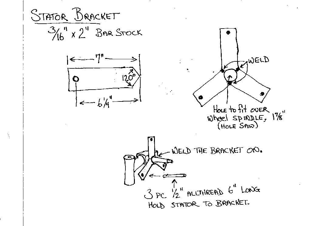
The drawing above shows the stator bracket I mentioned earlier, and how it will be welded to the assembly we've been making.
Here we see the basic frame for the windturbine with the stator brackets welded on. Now we can start really building the alternator!
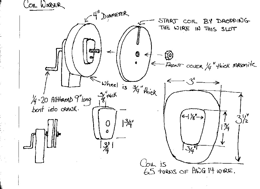
Above I've drawn some details about the coil winder I used. We need to make this because we need 9 nice tight identical coils. Each coil will be 65 windings of AWG 14 enameled magnet wire. Basicly the coil winder is made up of two disks 4" diameter. I drill them 1/4" in the middle so they fit over 1/4" allthread tightly. The shaft and crank are of one piece of 1/4 - 20 allthread with a crank bent on the end. The back disk in the winder is thick wood (1/4") and it fits tightly over the allthread and it glued on there. The center part of the spool is of 3/8" material - this is the part we'll wind the wire over. I like to sand it very smooth, and give it a slight taper (so the front is slightly narrower and shorter than the back) so that the finished coils slide off easily. The front of the coil winder has a slot so we can drop the wire in there and tie it off to the shaft when we start winding a new coil. Before using it, I wax it carefully. (well be putting glue on the coils and this keeps the coil from getting glued down!) We bolt the front on it, drop the end of the wire in the slot (leaving about 10" sticking out) - and wrap the end around the shaft to secure it. I hold the wire with tension in one hand while winding with the other, taking care to keep the wire reasonably tight, and the windings pretty neat. It goes very quickly. The drawing shows about the size the coils should come out. Once the coil is done, before removing it I put a bit of thin viscosity super glue on it. It soaks into the coil tightly gluing all the windings together and making the coil quite hard and tough. I then spritz the coil with accelerator and the glue dries instantly. It's a neat sort of glue, very handy! Click here to find that on our shopping cart. Once the glue is hard the coil should be easy to remove. Sometimes they are a bit tight and gentle prying with a butter knife or something helps.
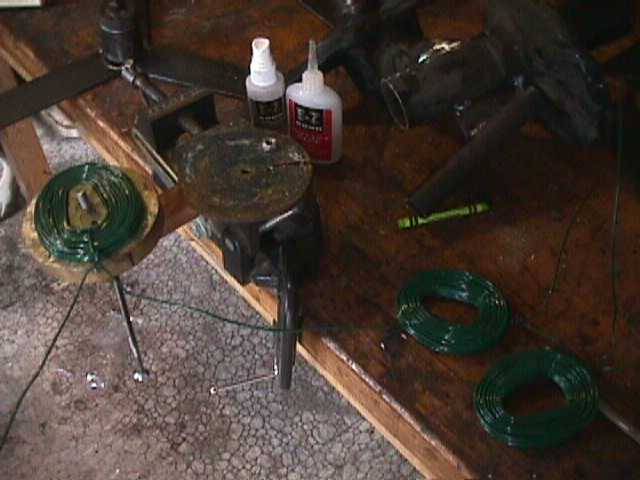
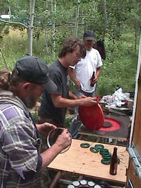
Pictured above is the glue, the coil winder with the lid off showing a coil... and a few coils I wound. Once all 9 coils are wound we're almost ready to build the stator! First we have to make a mold.
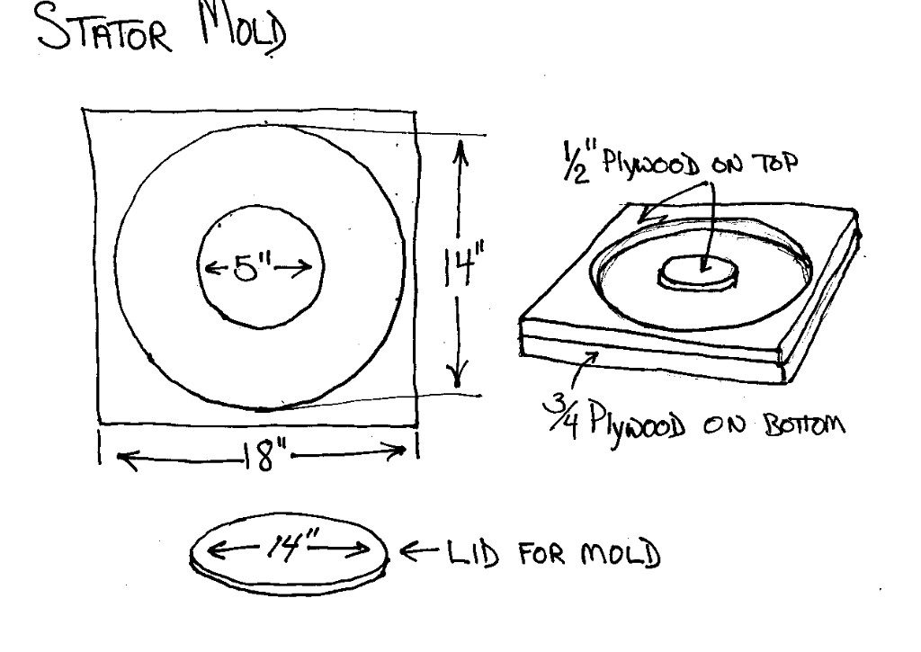
The mold we made is very simple, the picture above leaves little to be explained. It's all screwed together. It's important to sand it well, and leave the insides slightly tapered so that the casting will slip out easily. In the bottom of the mold I take a heavy black marker and draw lines at 40 deg to each other so that we have exact spaces to put our 9 coils. The lines should be heavy so we can see them through 1 layer of fiberglass material and some resin.
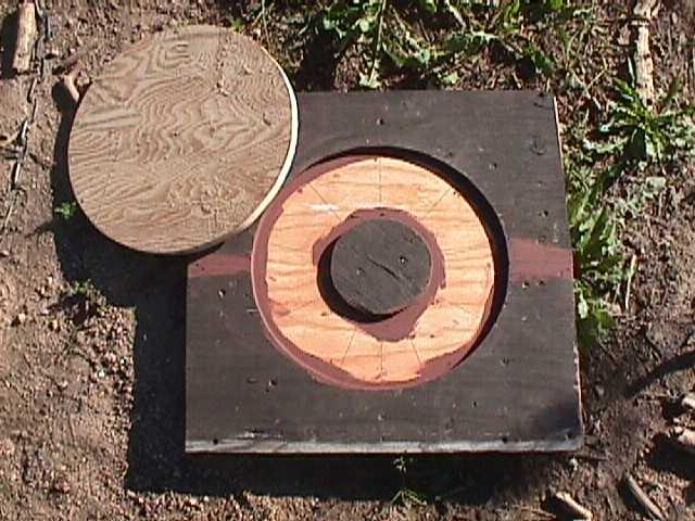
Pictured above is the finished mold. The dark purple spots are caulk we used to fill gaps and cracks between wood... this just helps the casting come out more easily. Before using the mold, we need to put some kind of release agent in there. Auto polish wax works great... we didn't have any so we used axle grease! Lard, butter... I'm sure lots of things would work fine!
We need some fiberglass in the stator for strength. Pictured above DanF is cutting out 2 rings of fiberglass fabric exactly the size of the stator, 14" diameter with a 5" hole in the middle. We'll have one of these on each side of the coils for reinforcement.
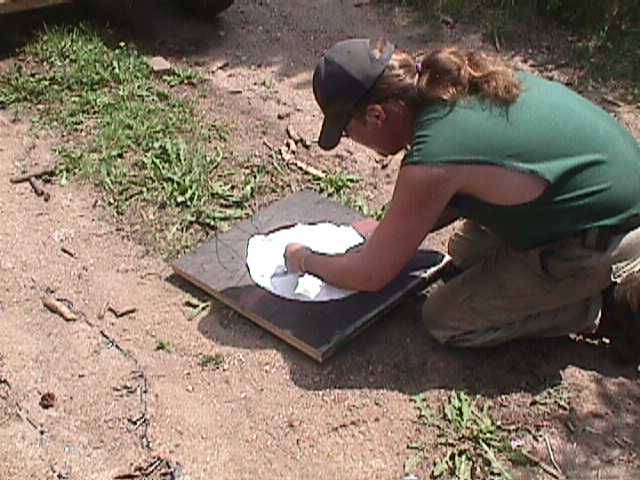
Pictured above we are wiping axle grease all over the mold to assure things will come out easily in the end.
We mix up a little polyester resin and put it in the bottom of the mold. Then we lay the fiberglass fabric over that, and pour a little more resin over the top. We work it in with gloves so the fiberglas is completely soaked in resin. At that point it becomes somewhat transparent so we can see the lines we drew in the bottom of the mold and we can tell exactly where the coils should be placed. Something to note about polyester resin: It smells bad! Some folks will get headaches... it's the sort of horrible smell that can stick with you for hours! A respirator is probably wise. You don't want it in your eyes, so safety goggles would be appropriate. It's sticky - messy, so wear latex gloves or something to keep it off your skin and hands.

Pictured above we've layed the coils in the mold, as you can see they fit pretty tightly! This picture is actually from an earlier machine so it's not quite right. Since then I've shortened the coils a bit and made the hole in the center of the mold a bit smaller so that the coils have less wire in them, lower resistance - and don't come quite so close to the outer edge of the mold. It's important to push the coils in towards the center of the mold as much as possible so they are existing directly beneath the magnet rotors. The leads from the coils should stick out the sides in an organized fashion. Each coil has a "start" - the inside lead, and an "end"- the outside lead - I like to keep them organized so that wiring them up is easy later on. At this point we mix up more resin and add some talcum powder - mix it up real well. By volume, a half and half mix is reasonable though it could be thinner. The talcum powder adds some strength and lets the resin go a bit further. We pour that into the mold till the coils are covered, and then lay on top the other fiberglass fabric ring. We can then mix up a little more resin (without talc) and pour it over the top making sure the fabric is completely soaked and transparent.
Once the resin is poured we put the lid on the mold and put lots of weight on it to keep things clamped down and flat. Best is to leave it like this overnight.... I get impatient and usually wait about 2 hours!
And here we have an almost finished stator! All we have now to make a functional alternator is to bolt it on, wire it up, and add a couple of magnet rotors. Lots of pictures in this page and LOTS more to go!
| PAGE 1 | PAGE 2 | PAGE 3 |