
Built using a digital bicycle speedometer
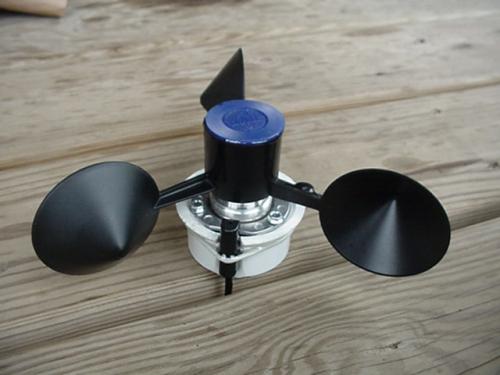
The completed anemometer cup and sensor assembly.
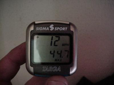
Sigma Sport Targa digital bicycle speedometer -- about US$25 at any bike shop.
UPDATE 3-29-2006 ---- We are OUT OF STOCK on the surplus brushless DC motor we used to build this project, and since it's surplus we cannot get any more. You can use a different motor (for example, something salvaged from a dead hard disk drive) because this design depends on the motor only for its bearing -- the internal coils don't factor into the output frequency. You could also use a standard small bearing, available at most good hardware stores. Stay tuned, and feel free to ask questions on our Discussion Board.
DanF's Easter Egg Anemometer has been up and flying beautifully for 2 years now. This new design is much easier and quicker to build, but costs a little bit more initially. We learned how to build it during our trip to Guemes Island, WA for Hugh Piggott's homebuilt wind power seminar for SEI. It uses a digital bicycle speedometer to count pulses from a magnet and reed switch on the anemometer cup assembly, and the speedometer translates this automatically to mph or kph. It also keeps track of your maximum gust, average windspeed, and total wind miles -- so it works as a wind odometer too! Very useful for doing wind power site evaluations.
Parts List
- Digital Bicycle Speedometer -- We used a Sigma Sport Targa because of the peak speed, average, and odometer features. It's available at almost any bicycle shop for about US$25.
- Anemometer Cup and Hub Assembly -- You could use any commercial or homebuilt cup assembly for this. Check out our Easter Egg Anemometer page for details on how to build your own.
- NdFeB Magnet -- The magnet that comes with the speedometer is a rod shape, and we found it easier to fit a 3/8 inch diameter by 1/16 inch thick disc magnet to the cup assembly rather than the rod. It's Item #75 on our Shopping Cart, and costs only US$0.20.
- Bearing Assembly -- Many different designs of bearing assembly will work. You want it to spin as freely as possible, so you can get better response and also measure very low wind speeds. For this project, we used the same ball bearing DC brushless PM motor as in our Easter Egg Anemometer, and we removed the coils to make it spin more freely....we just need the bearing for this project. The motor costs only US$2.50. It's Item#2105 on our shopping cart. You could use any sort of bearing assembly you can devise from scratch, just make sure it spins VERY freely.
- PVC reducer fitting -- 2 inch to 1.5 inch white PVC reducer coupling.
- 3 Machine screws -- #4-40 , 1/4 inch long.
- Glue -- epoxy, PVC cement, and thread lock compound are needed.
- Tap -- a #4-40 tap, available at hardware stores.
- Mounting supplies -- 1.5 inch diameter PVC pipe for mast; telephone or other thin wire to extend sensor wire.
Assembly
Cut the PVC pipe reducer off with a hacksaw right at the flange, on the big 2 inch side. This gives a wide, tapered rim surface to mount the bearing assembly to. See photos below. Using a file, cut a notch in the flange just big enough to fit the sensor from your bike speedometer. Cut it deep enough so that the sensor can ride flush with the pipe.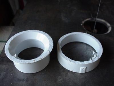
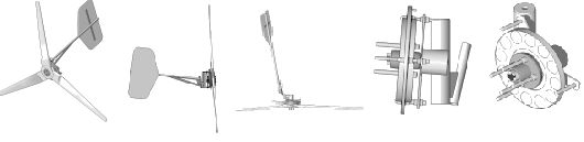
Place the bearing assembly upside down in a vise so it's suspended by the flange. DON'T tighten the vise. Gently tap the center bearing loose from the back using a Phillips screwdriver and small hammer. Or press it out on your drill press. Gently pry the coils out using a flathead screwdriver. Gently press the motor back together -- if you go all the way back in now, the motor will bind and not spin freely!
Optionally, you can skip that entire step. However, there will be a bit more resistance in the bearings from cogging, and it will take a couple more mph of wind to set your anemometer spinning. By prying the motor open, you also risk bending and ruining it. So you might want to have an extra available if you try this. The performance difference is very small with the coils left in. Our success has been mixed with removing the coils from these motors -- it's hard to get them back together so they are tight but still spin freely.
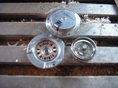
Disassembled Motor
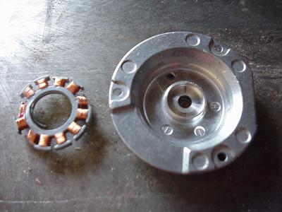
Coils removed from Motor
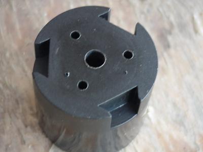
Drill out the center of the hub with a 1/4 inch hole. The exact center is already drilled with a tiny hole, so it's easy to get it perfect.
To mark the anemometer hub for drilling the mounting holes, we cut off 3 small nails with wirecutters, and dropped them point-up into 3 of the small holes in the motor. We then centered the hub around the motor shaft (si it does not touch the shaft) and pressed down to mark the holes. See photo below. Then drill your 3 holes.
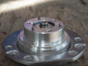
Nails in motor for marking hub holes.
Completed anemometer hub assembly
Now, tap your 3 mounting holes in the motor. Don't push any deeper than the holes already are, or you will distort the metal and sieze up the bearing -- it'll be ruined. Assemble the anemometer cups onto the hub -- they press in, but you have to press hard! Put thread lock compound on the #4-40 machine screws, and attach the cup and hub assembly to the motor. Try it, and it should spin freely by just blowing on the cups. This is essential -- it should spin in the slightest breeze. And it should be nearly perfectly centered on the bearing. To seal the top (acutally the bottom, after mounting the thing upside down) we just epoxied a poker chip on there to cover it -- perfect size!

Completed anemometer hub assembly, mounted in PVC reducer, with sensor attached.
Next you'll need to install the trigger magnet and rpm sensor switch, then mount the cup, hub, and bearing assembly into the sawed-off reducer. Mount a small NdFeB magnet to the inner shoulder of the cup assembly with epoxy. Use a file to notch the PVC reducer mount to accept the sensor that came with the bike speedometer. We simply used epoxy to glue the sensor tightly in the notch. Be sure to test the sensor before glueing it into place! The range at which it will trigger depends on the location and strength of the magnet. Ours triggered best at about 1/8" clearance between the magnet and sensor. We found the sensor triggered best by pointing the small end of it right at the magnet (see picture above). The sensor wire with the speedometer is only a couple feet long, so we snipped it and used telephone wire to extend it to 20 feet long, so it could run right into the house for mounting the speedometer disply inside. We used small machine screws and epoxy for mounting the bearing assembly.
Finished unit, ready for pole mounting.
Because of how our bearing assembly is built, there's a big chance that water could get down inside the bearing assembly and ruin it. So we opted for mounting these anemometers upside down, with the mounting pipe pointed down. The mount can be any design you come up with with 1.5 inch PVC pipe, using Tees, 90 deg bends, anything that fits your mounting area.
Testing and Calibration
For testing the new anemometer, I once again used my truck testing rig. It's simply a pipe mounted in the bed of my pickup that sticks up 6 feet over the top of the cab. Just be careful about overhead power lines and branches while you are testing! The only problem with truck testing anemometers -- is that even the slightest breeze will completely destroy your test results. You'll need to find an absolutely breezeless day for calibration. If you already have another anemometer that's calibrated (or rent one from the local renewable energy store for a day), you can just mount your new one near the old one and compare the readings.
The bike speedometer uses the measured circumference of a bicycle tire to calculate the bike's speed, using the number of tire revoluitions per minute as tallied by the sensor mounted ot the bike and the magnet mounted to the wheel. But with anemometer cups, there's a bunch of 'slip' involved -- the cups to not catch all the wind that goes by. So you can't just enter the anemometer's circumference into the speedometer. That's why calibration by some method is required. With our 2 anemometers, the offset number entered into the speedometer was 1320 (mm). If your unit is showing a higher speed than the truck or test anemometer, you increase the diameter that you enter into the computer. If your anemometer reads low, you decrease the diameter. A change of 5-10 mm makes a big difference! But after fiddling with it for a while, you should be able to get very close. If you get widely varying readings -- there is probably too much breeze for testing.