After building the all wooden windmill I felt inspired to make a larger and sturdier version. The following page offers a brief description of building the alternator and testing it. I designed this alternator WHILE I was building it, using mostly intuition and working around supplies available. Undoubtedly many improvements could be made. If you have any ideas or thoughts about this, please share with us via email or our discussion board!
Para Español, traducción de Julio Andrade.
Initial test results--wired in series, reaches 12 volts for charging at 120 rpm, with 6 amps charging current at 300 rpm. Wired in parallel, reaches 12 volts at 240 rpm, with 12 amps charging current at 350 rpm. At 500 rpm it produces about 500 watts. Unfortunately this is the limit of our current testing rig--we need to build a bigger one. More tests and a chart to come!
Parts and supplies used
To build the alternator I used the following:
10" long piece of shaft, 1/2" diameter.
2 1/2" inner diameter ball bearings
18 surplus NdFeB rare earth magnets
3/4" plywood
5 Pounds 18 AWG magnet wire
1 1/2" drywall screws
3" deck screws
Epoxy
Super Glue
Fiberglass resin for final finishing
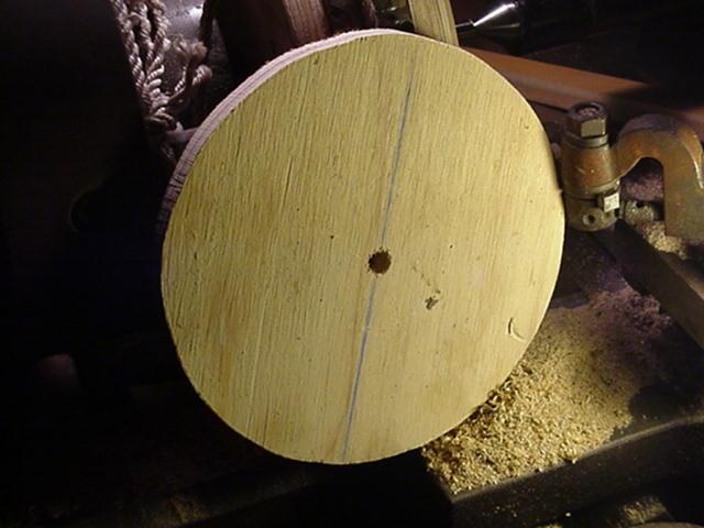
I cut out 5 plywood disks on a bandsaw, 9" diameter. In the center of each disc I drilled a 1/2" hole. These disks are laminated on the shaft to build up the armature. In order to hold the armature securely to the shaft, I drilled a hole about 4" from one end 1/8" diameter, and inserted the a pin, 4" long. On one disk I routed a slot, 4" long and 3/16" wide, 3/16" deep, to accept this pin so that it would be locked to the shaft. I generously coated the plywood discs with wood glue and clamped them together on the shaft, then screwed them together with 3" wood screws.
On the metal lathe (a wood lathe would work fine) I evened up the armature so that the diameter is approx 8.75". In the center of the armature I cut a slot 3/16" deep exactly wide enough to accept the magnets (1.74"). The magnets are laid in with alternating poles facing up. This particular magnet is available with either North or South on the outside. This alternator requires 9 of each variety. The diameter is such that the magnets stick out from the wooden surface of the armature, so the total diameter, magnets included of the armature is just short of 9.25". These magnets have an arc much more acute than that of the armature, so it looks kind of "lumpy"! I don't think this is a problem. Custom magnets simply cost too much, it often pays to work with that which is available. In order for 18 magnets to fit around the armature, there is a small space between each magnet (approx 0.10"). For spacers, I used 1" drywall screws, which were removed after the glue dried. Since they are tapered at the top, simply screwing them in deeper provides for a larger gap between the magnets, so...with a little patience, it is easy to adjust the screws and get the magnets evenly spaced around the armature.
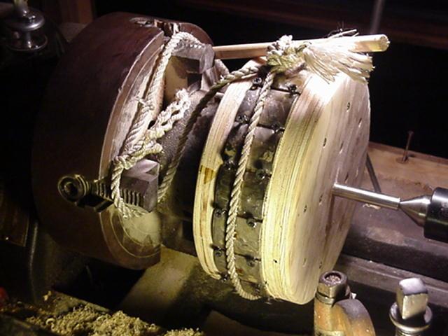
Once all the magnets were pressed in place, properly spaced with screws, I glued them in with epoxy. As a clamp, I simply tied a rope around the magnets and tightened it with a stick through the knot. When the glue started to set up hard, I removed the screws and applied a new coat of glue over the entire surface of the alternator. This not only aids in holding down the magnets, but it will protect the alternator from moisture.
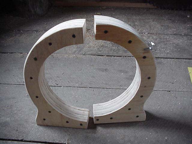
The stator (that part which will eventually hold the coils of wire) is built up of 3/4" plywood. The inner circle has radius of 5", which leaves room for coils between it, and the armature. The magnets protrude from the wooden alternator approx 1/8", so this allows for coils to be approx 3/8" thick and have close clearance with the magnets. A very small gap between coils and magnets is important, especially if the coils do not have a ferrous core. I cut pieces to build up the stator from the plywood and glued them together, clamped them tight and screwed them together with 1 1/2" drywall screws. Each piece is made up of 3 laminates, for a total thickness of 2 1/4".
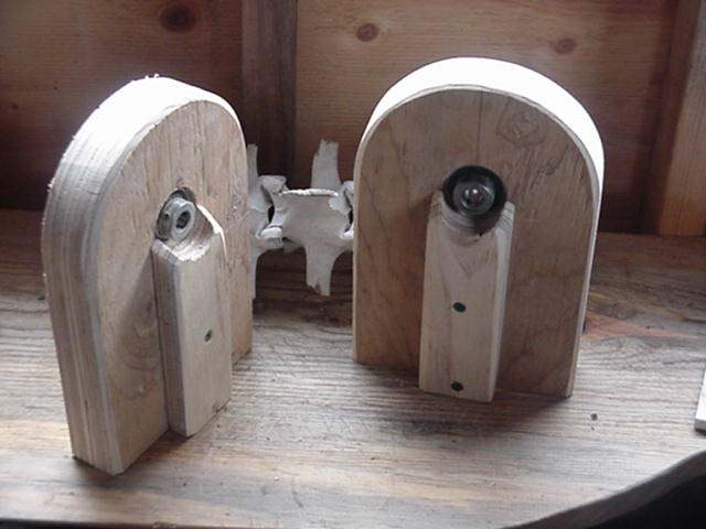
The shaft is supported by pillow blocks, also built up from 3/4" plywood pieces. I cut holes with a 1 1/2" hole saw to accept the bearings. Of course, the bearings have 1/2" inner diameter to accept the shaft. The outer diameter of the bearings is roughly 1.6" inches - a very tight press fit into the holes in the plywood. I coated the outside of the bearings with epoxy and pressed them in with an arbor press(a vice, or hammer should work fine too), as deep as possible so that I could still tighten the set screws. I was pleased with how well they fit the holes, and how straight they pressed in. I believe I got a little lucky here!
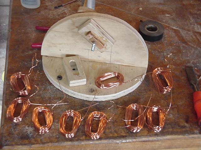
I built a simple coil winding device to speed production. It has a crank on one side, and a spool on the other. I used a long bolt as a shaft, and the end of the spool is held on with a nut. Each coil is wound on the form, then the nut is removed...so that the end of the spool comes off and the coil can be removed. It went very quickly! Since the alternator has 18 magnets, I wound up 18 coils. The coils are of AWG 18 enameled magnet wire, each coil has 50 wraps. The coils are approx 2.75" X 1.5" on the outside, and the hole in the middle is approx .5" X 1.5"....as per the size of the spool on the winding machine. I thought this was an appropriate size, considering the size of the magnets. Really - it's somewhat of an intuitive guess...
When the coils come off the winding machine, they are fairly loose, and delicate. I handled them carefully before gluing them into the stator laminates.
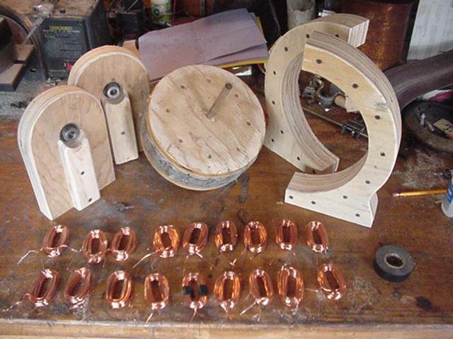
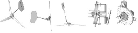
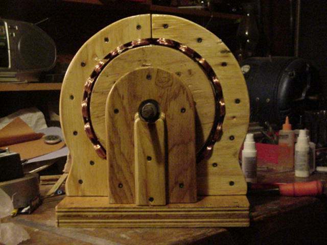
In the above image you can see all the parts of the alternator ready for finishing and assembly.
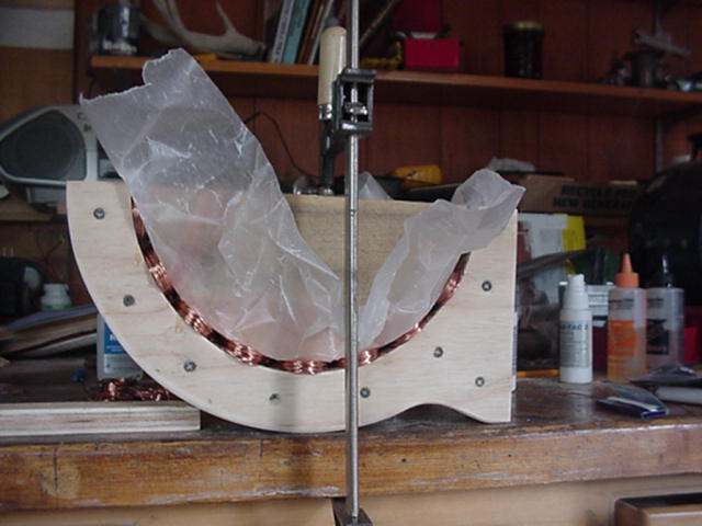
For the first step in attaching the coils (not shown in any pictures) I measured out their proper location (they must be spaced evenly) and lightly tacked them in with super glue. Then I generously coated them with super glue (epoxy would also work fine...it would just take longer), covered them with wax paper, and clamped them in using a form I cut from wood. This form forces them into exactly the right diameter to fit around the armature. Once the glue was dry, I removed the clamp, the wooden form and the wax paper, and was pleased to find they fit very well! In the future, I may fill the center of these coils with a mixture of magnetite sand and epoxy - this would help conduct the magnetic field through the coils, and increase the current output of the finished alternator. For now, I'm very curious to find out how it perfoms with nothing but air between the coils. There is also an advantage to "air cores" inside the coils--the alternator will not cog at all until under a load, which eliminates much vibration and will help the alternator start spinning in some applications. Cogging is a problem in permanant magnet alternators, especially for wind generators.

After the coils are glued in, all that remains is sanding and finishing. Thankfully I had some help from our head of research, development, and particle physics....Maya!
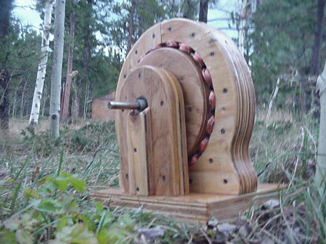
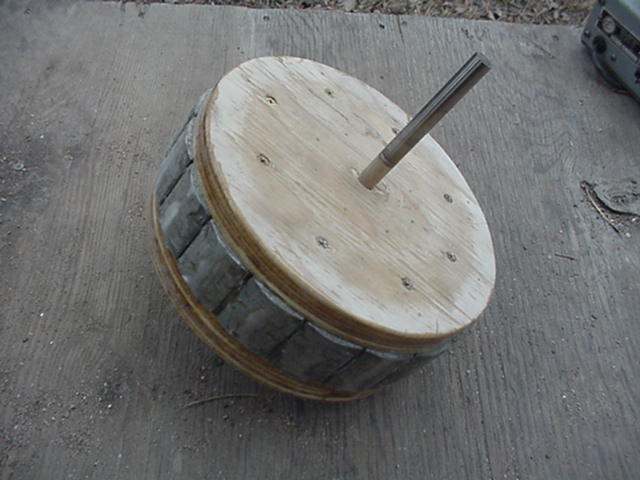
All the parts were generously coated with fiberglass resin - kind of like epoxy, it makes a thick, plastic coat and should make the alternator practically waterproof for years to come. The only drawback...it stinks real bad! You can get this stuff at any hardware or auto parts store. Difficult to see in this picture, but...the base of the alternator has wooden dowels in it, so that all the parts can be exactly located in their proper position whenever the unit is assembled. This allows for easy assembly and disassembly. When making the base, I put the parts together so that it spun easily--the coils were as close as possible to the magnets, and nothing rubbed. Then, I tacked the whole alternator together lightly with super glue and drilled 1/4" holes up from the bottom of the base into the pillow blocks, and both stator halves. I then glued into the base 1/4" dowel pins which assure that whenever assembled, all the parts will fit exactly into the right places.
After the fiberglass resin set up, I assembled everything on the base. Everything fit well--the clearance between coils and magnets was excellent. Once all looked good, I screwed it together from the bottom with 3" deck screws. It seems very sturdy--nothing moves, rubs or vibrates that's not supposed to! At this point I wired all the coils on each stator half into series. The coils must alternate in the direction they are wound. It can seem confusing! Trial and error isn't the worst way to be sure it's properly wired. Simply spin it slowly by hand, and start measuring voltage, starting with one coil, and being certain that the voltage increases with each additional coil which is wired in series.
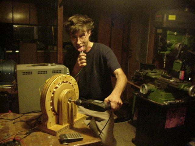
All the coils on each half of the stator are wired together in series. At that point, each half can be hooked in either series or parallel to most appropriately match the load with the alternator. Above is pictured the good old Taste Test, a sure fire way to test any battery, or generator, as long as it stays below about 10 volts! (otherwise it hurts--don't try this at home!)
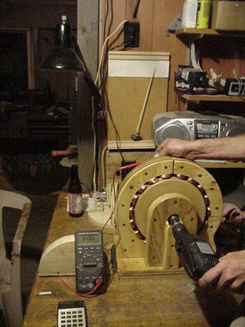
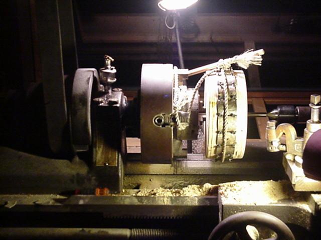
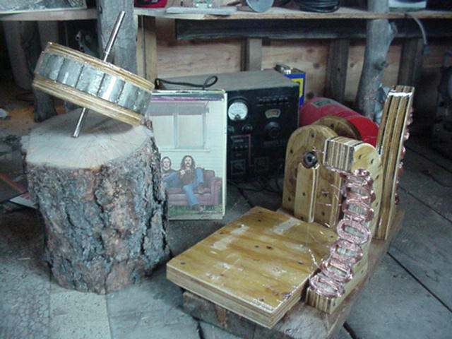
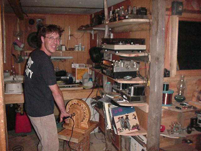
I don't have proper equipment to fully test this alternator. The best tool I have, since it will not fit on my lathe, is a hand drill with a 1/2" chuck. With a meter which reads frequency, I am able to accurately tell rpm. When both halves of the stator are hooked in series, the alternator will reach 12 volts at approximately 120 rpm. At approx 300 rpm, it charges approx 6 amps into my batteries (this is the limit of my hand drill!). When I hook both halves of the stator in parallel, it hits 12 volts at approx 240 rpm, and at approx 350 rpm it's charging slightly over 10 amps into my 12 volt batteries. In the picture above you can see the frequency meter, and the large wooden ammeter on the wall. Clearly the limiting factor here is the power of the hand drill. I'll post a chart when I build a good alternator test machine and get some better results! All things considered here, I'm very pleased with the results.
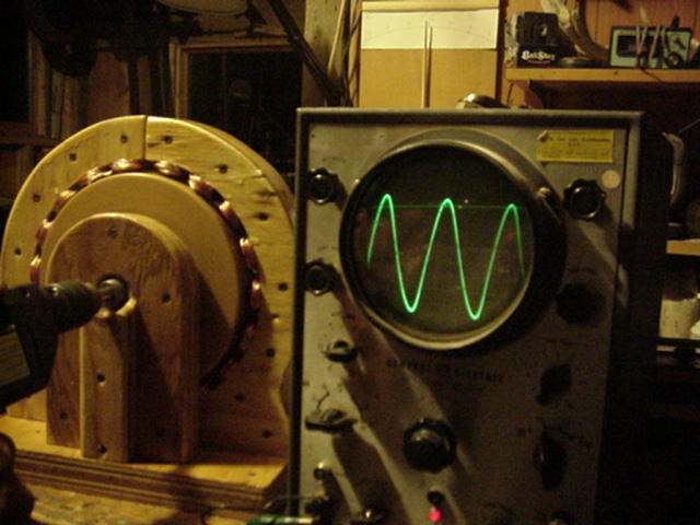
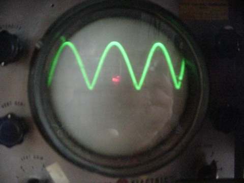
I was curious what the output would look like on the scope, considering the close proximity to one another of the magnets, and the "lumpy" armature. Keep in mind, what is shown above on the scope, is Alternating Current, directly out of the alternator. In order to be useful in batterycharging, it must be rectified into Direct Current. To do this a "bridge rectifier" (a simple arrangment of 6 diodes) must be used.
Shown above is the "rectified" output of the alternator. This is useful for battery charging, but - you'll notice how "lumpy" the Direct Current looks on the scope. Although this rarely causes problems, occasionally this sort of Direct Current will cause problems with radio and television reception (you'll hear a whine). To help smooth out the Direct Current available here, a capacitor can be used.
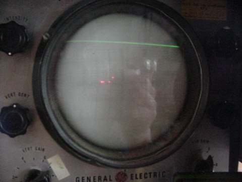
See above the nice, flat DC output after a capacitor is hooked up between Pos and Neg outputs.
Just for fun...I hooked it up to my stereo! This is a CD player, hooked to a '50's Fisher vacuum tube preamp, hooked to a Dynaco Stereo 70 vacuum tube power amp. If you add up the numbers on the back of these...it totals over 300 watts. To my amazement, this wooden alternator lit up the tubes and the CD player...played music and sounded just fine, when powered by the electric hand drill! The hand drill is rated to draw maximum current of about 3.5 amps...so this is a reasonably efficient transfer of power!
In conclusion... This whole thing took about two full days time, about $100 in magnets and $30 in magnet wire. (The shaft and bearings I had on hand) Not a bad price for an effective low rpm alternator. It was also fun, and the information obtained is useful. Using premade pillow block bearings would probably be wise, especially if one intended to really use the alternator! There are certainly easier ways to build alternators which would be just as, or even more effective. To build this really requires a lathe, bandsaw, drill press...etc. If one built a similiar machine using a disk type armature instead of a cylinder, it would be much simpler. I stuck with this design only because it seemed fun, looked neat - and was based upon my earlier wooden windmill. Keep your eyes peeled for our next alternator..it'll be even easier to build and much more effective. Overall though, I'm surprised with the performance fo this unit, considering it contains nothing but air between the coils and wood all around. Wood is a lousy conductor of magnetic fields! Just goes to show...it doesn't have to be optimal, it just has to work!
It seems that there may be some argument for not worrying too much about steel laminates, or ferrite cores in the coils, and simply adding a few more magnets and wires and settling for a somewhat larger machine. One immediate benifit of having "air coils" is obviously the complete lack of cogging, which, if used in a windmill should result in a machine that starts very easily. I have no idea at this point what the maximum output of this alternator might be, but preliminary tests are impressive in my opinion! One could build a fine wind or hydro plant with such a machine. As with all our other alternator "experiments"...it is truly the magnets which make it possible! Without these super high quality magnets, this alternator would not be nearly as effective. With normal ceramic or AlNiCo magnets, one would have to go to much greater lengths to build a alternator which efficiently produces this kind power at such low rpm.