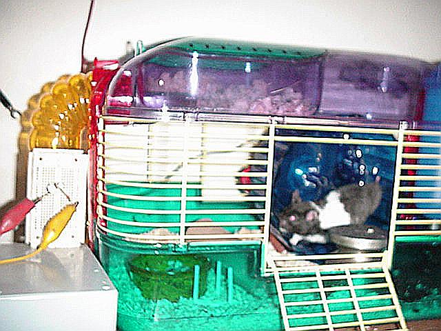
Though Skippy the Hamster powers this night light by running on his excercise wheel, the same concepts and low-rpm alternator design could be applied to a school science project using different energy sources! A small wind or hydro turbine could easily power this alternator.
The Otherpower.com staff thought of building a hamster-powered nightlight a couple years ago at a rather, uh, soused company Christmas party. Then recently Analise, an 8th grader from Albuquerque, NM, contacted DanF through the AllExperts.com Science For Kids forum, asking 'Can a rodent generate enough electricity to power a light by running on it's wheel?' That was enough inspiration for us to start the project, and we soon added Skippy the Hamster to the Otherpower.com payroll. He's a Syrian Hamster, and we chose that breed since they are nocturnal and like to run on the exercise wheel. Analise will be using a mouse named Ghost for her science fair project.
Skippy the Hamster
The first criteria we needed to design the alternator was an estimate of the Revolutions Per Minute (RPM) a rodent can generate on the wheel. The lower the RPMs, the more difficult it is to design a good alternator for it. Analise took a stopwatch to the local pet store and recorded how many times the wheel went around in 10-second intervals, then multiplied these figures by 6 to get RPMs. She found that most rodents can make between 40 and 60 rpm on the exercise wheel. That gave us a starting point for the alternator design.
Our first thought was to use a DC hobby motor to generate the electricity, so we could charge up some NiCad batteries to run a light. However, we immediately ran into the same problems as when we built toy wind turbines using hobby motors -- at the required low RPMs, most hobby motors cannot get the voltage high enough to start charging batteries. And you often can't tell what a hobby motor is rated at, there is not usually a specs plate on it. So you might have a 500 RPM motor, or a 10,000 RPM motor! The rated RPMs of the motor determine at what RPM it can make a certain voltage. None of the DC hobby motors we had available could make even 1.2 volts (the voltage of a single AA NiCad) at 40-60 rpm. So we scrapped the idea of using a DC motor as a generator. Plus, the required diode (to keep the battery from just spinning the motor) would drop the voltage by at least another 0.7 volts. It would be possible, but complicated (and bad practice) to use gearing or a belt and pulley system to raise the RPMs -- the friction losses in the gearing system would be major, and design would be complicated. Rodents like to chew, and a rubber belt would be fair game. Plus it's much more fun to build your own alternator than to use a pre-made hobby motor!
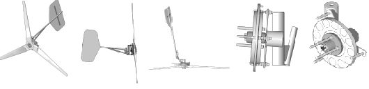
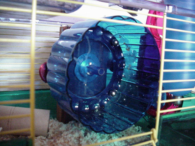
Frame and Bearing Construction So, we chose to scratch-build a tiny low-RPM alternator for the hamster wheel. The first issue we noticed is that the wheel that came with the cage was noisy when Skippy ran on it. VERY noisy! That meant that some of Skippy's energy was being converted to sound by mechanical vibration--and we want all of his energy to go into power production! So the first thing we did was modify the wheel with a new ball bearing. We simply used an inexpensive surplus DC brushless motors. Although the design of the motor itself is exactly like a permanent magnet (PM) alternator, these motors can't produce enough power to even light an LED at low RPMs. We used it simply because it was a cheap source for a really nice little ball bearing, and was easy to mount the wheel to. You could use any free-spinning bearing that's available--off an old skateboard, rollerskate, anything that spins freely and you can mount the wheel to.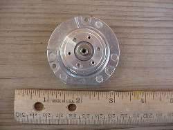
Surplus brushless DC motor used for the ball bearing inside and easy mounting
To mount the wheel to the motor, we simply centered it on the wheel and marked 3 holes from the top of the hub for drilling. The motor hub has 6 holes--3 are tapped to a weird little SAE 2/56 thread, the other 3 are blank. We used a simple 4/40 tap to thread these smooth holes to fit 4/40 machine screws, and mounted the wheel to the motor hub with these. The motor was then mounted to a thin piece of wood. The entire wheel is free-standing on this wooden bracket -- it does not have to mount to the side of the rodent cage.
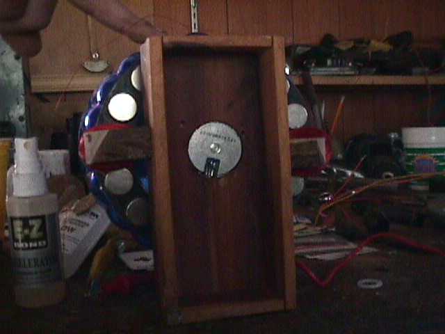
Wooden frame showing motor mounting, from back side
Permanent Magnet Alternator ConstructionThe next step was building an alternator onto the wheel. A big advantage of using a Permanent Magnet (PM) alternator for any kind of power generation is that no brushes are required for electrical contact to the spinning part (the armature, also called a rotor)--the magnets spin, and are not connected to the coils in any way. So we simply fitted a steel ring with magnets evenly spaced on it to the flat side (the axis) of the wheel. This makes it an 'axial-flux' alternator....if you fitted the magnets to the curved surface of the wheel around the circumference it would be called a radial-flux alternator.
alternator mounted to back side of wheel
We cut out a ring of approx. 16 gauge steel to fit the wheel. You could easily use 2 coffee can lids stacked and cut out for this-- you could use a drill and tin snips for this. We used a hole saw for the inner circle and a bandsaw for the outer. Be careful, when the steel is first cut the edges will be very sharp! Grind them down with a wheel or file so they are safe for both you and your rodent. This steel ring behind the magnets forms a more complete magnetic circuit so there's more flux passing through the stator coils. It also makes it much easier to mount and evenly space the magnets, since they stick to it.
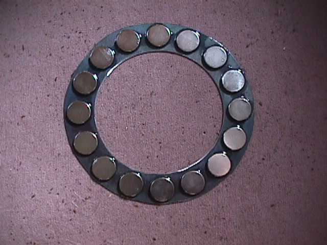
Magnets mounted on steel ring
We chose the magnet size with the limited amount of power a hamster can produce in mind. 3/4 inch diameter by 1/8 inch thick Grade N-35 Neodymium-Iron-Boron magnets. Very powerful, but not too heavy. You can make up for lots of design and mechanical tolerance problems by using very strong magnets in a homemade alternator! If you use weaker magnets, your power output will be significantly reduced. We used 14 magnets because it was the largest EVEN number of magnets we could space around the ring, so this may vary depending on the size of your rodent's wheel. You must use an even number of magnets. We spaced them evenly using playing cards...by trial and error we found the right number of cards to use as a shim between each magnet. It's important to get them spaced evenly. The magnets also must be placed with the North and South poles alternating on each magnet. And the edges of the magnets should be aligned in a perfect circle, too. Read on for magnet mounting details.
Compared to the giant, finger-breaking magnets we used in our 10 foot wind turbines, these little magnets are pretty safe and easy to work with. They are, however, powerful enough to pinch skin and give you a blood blister, so handle them carefully and keep out of reach of young children. Parental guidance is needed for older kids too.
First, place one magnet on the steel ring and center it between the inner and outer edges of the ring. Tack it down with a drop of cyanoacrylate glue (Superglue®) applied around the edges--be sure to use thin viscosity glue, so it will wick underneath the magnets and set up. It also helps to have glue accelerator around--one spritz of this and the glue sets up instantly (keep your fingers out of the way!). Now each magnet must be placed with the opposite polarity of it's neighbors facing out. To get this right, carefully take each new magnet off of the stack, and carefully hold it up to the next magnet mounted on the ring. If it repels, hold the magnet exactly as it is oriented and gently snap it to the ring. Use this test for placing each magnet, and check it when you are done....the magnets should alternately repel and attract the magnet in your hand as you go around the ring testing. Remember, you must always use an even number of magnets. After they are all placed, use playing cards to space them so they are aligned evenly around the circle. And make sure they are aligned in a perfect circle radially too -- check the inner and outer diameters of the circle of magnets and slide them around to get perfect alignment both ways. When everything is good and you've checked to be sure the magnets alternate in polarity, tack all of them down with drops of thin superglue appied around the edges of the magnets.
To make things simple, we simply centered the magnet disc on the back of the plastic hamster wheel, and held it in place with 4 more strong magnets stuck to the inside of the wheel! This makes it easy to remove, but still holds it tightly on there. You could also use glue if needed. Remember also in designing your mount -- the magnetic field from the magnet disc should be away from metal cage bars or other metal parts.....it will be attracted to these metal parts and will be slowed down significantly.....you'll be wasting lots of hamster power. And use caution handling the disc -- it will be powerfully attracted to ferrous metal or other magnets.
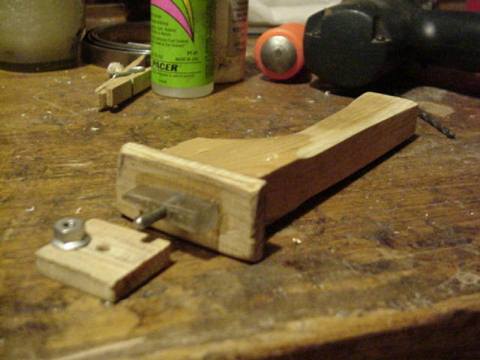
The next step is winding the coils. We wound one, tested it, and found we needed more voltage, so we ended up using 2 coils. Each coil is 400 turns of #30AWG enameled magnet wire. We used a simple hand-held coil winder, and made up a new center insert to get the coils the right size. The inner hole of the coil should be about the same size as each magnet you are using. You could also wind the coils around a tube that's the right size, but the elliptical coil shape we got by using a winder performs a little better, and the tapered form in the middle makes it easier to get the finished coil off of the winder. The important thing is to pack the wire in there as evenly and tightly as possible.....the finished coils should be about 1/4 inch thick, with each leg of the coil about 1/4 inch wide and the center hole matching the magnet size. Here's a detail of how we built the winder:
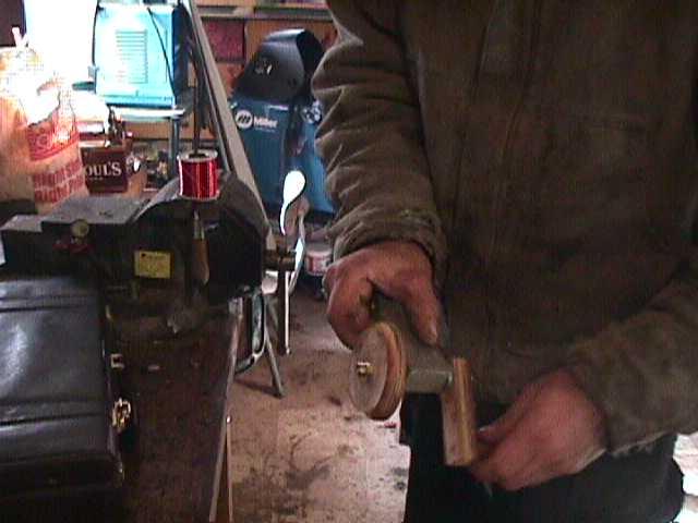
Here's DanB winding a coil. Notice how the spool of magnet wire is on a pin in the vise to permit easy feeding. We also wax the winder form with crayons so superglue won't stick to it...makes it easier to remove the finished coil. Leave a big tail on both ends of the magnet wire.
Once you get 400 turns on the coil, twist the leads together so the coil won't unwind, and drip superglue into the coils. We then hit it with accelerator to speed the drying time. Then disassemble the winder and carefully remove the coil. Hit it with more superglue if it wants to come apart on you. At this point you can even spin the wheel and hold the coil up near it by hand. In our first test we showed about 1.2 volts AC when doing this. That told us we needed another coil, which will double the voltage when hooked in series and in phase with the first coil. You'll need to strip the wire ends with sandpaper, razor blade, or knife before connecting.
At this point you can mount the first coil. We simple glued it to a small block of wood and glued this to the frame. Get the coil as close to the rotating magnet ring as possible without it touching. We ended up with a big airgap here due to the wobbly motion of the wheel....about 1/8 inch. But the big magnets make up for this tolerance flaw. You should get an AC voltage reading now from the mounted coil when you spin the wheel. We could get more power out of the coil by mounting laminates or another magnet rotor behind them, like we do when building wind turbine alternators. But we decided that Skippy probably wouldn't care either way, and one side of the magnetic circuit open made for much easier construction.
Closeup of mounted coil.
Next we wound the second coil, identical to the first one. Here, however, it's very important to orient and mount the second coil correctly! It should be placed exactly the same way as the first. The easiest way to figure this is to use a voltmeter. Connect one lead of the first coil to one lead of the second coil and set your meter for AC volts (remember to strip the insulation off first). Hold the second coil away from the alternator and spin the wheel. You'll see the voltage from the first coil. Hold the second coil up to the alternator and spin it again. If you see approximately double the voltage, it is placed right. If you see no voltage, it's backwards. Flip it 180 degrees, so the other face points towards the magnets. When you know you have the coil oriented right, glue it to your mount (like with the first coil, we used a small block of wood that can then be glued right to the wooden alternator frame).
You also must place the second coil in phase with the first. The easiest way to do this: Have a helper hold the wheel so that the coil is exactly centered on one magnet. While your helper keeps the wheel from moving, place the second coil so that it is also exactly centered on a magnet and glue in place. We placed ours opposite each other, but you could place the second coil anywhere -- right next to the first, or whatever you want, as long both coils are centered on a magnet when you place them.
Now you can test the alternator. You should again see about twice the voltage you saw with one coil. If not -- first make sure all the wires are thoroughly stripped! It's trickier than you'd think. It's also possible you got a coil reversed. Try flipping one coil over and see if that works. And also check to see that a magnet is aligned exactly over both coils at once, so it's in phase.
Data Acquisition
Bicycle computer for data acquisition.
Next, we want to install the data acquisition computer for the system. We used an inexpensive bicycle computer, available at any bike store. The trigger is simply a cylidrical NdFeB magnet, and comes included with the bike computer. We disassembled the sensor and trigger to show how they are constructed. You don't have to do this unless you want to. The sensor is simply a reed switch connected to the computer -- I had already used the sensor from this computer for another project, so I just got another reed switch and made a new sensor, shown below. Again, you don't need to do this unless you want to.
magnet trigger glued to outside radius of wheel
Reed switch trigger
We simply taped the reed switch sensor to a small piece of wood and glued it to the frame. The magnet must pass within 1/8 to 1/4 inch of the sensor to trigger it. Now you need to tell the computer the circumference of your rodent's wheel, in millimeters. There will be a special button for setting the wheel size, consult the owner's manual of the bike computer. Skippy's wheel turned out to be 540 millimeters in circumference. After the computer is set, spinning the wheel should show you a miles per hour reading! Skippy does from 2-3 mph at normal speed, and slightly faster when DanF's cats are leering at him through the cage walls. The computer will also keep track of maximum speed, average speed, time spent on the wheel, and total miles run for you. We just got Skippy's system up and running, so we don't have any data yet for average hamster-miles per night yet.
Lights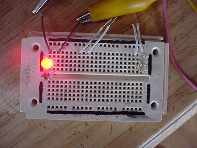
As we mentioned before, we were not able to get enough voltage with this simple 2-coil design and low rpms to charge a battery. The losses from rectifying the AC output of this alternator into DC would be very large...over half the voltage made. We could double the number of coils or number of turns of wire -- but then the resistance in the coils is getting very high, and the machine runs inefficiently with more than half it's output going to make heat instead of light. These are the exact same sort of trade-offs we must make when designing alternators for home wind turbines too! However, the opportunity for experimentation is excellent. Adding more coils would be one way to do this. With enough voltage to overcome the drop from rectifiers, a self-contained system could be built. An LED nightlight that turns on automatically when it gets dark, run off a rechargable battery, charged by the hamster alternator. Please drop us an email if you experiment more with this project!
So, we decided to run 2 super-bright red LEDs off the alternator directly. We chose red because they need the least voltage of any color to light up.....about 2 volts to get real bright. Other colors will work too, but they need higher voltage and therefore won't be as bright at any given speed. LEDs only pass current in one direction, so we connected the 2 backwards from each other....when one is lit, the other is off. The frequency of the flicker changes as the hamster changes speed. The light is bright enough in DanF's living room to find the bathroom at night when Skippy is running. Run Skippy, run!
Experimentation and Rodent PsychologyAnother interesting fact -- though it's hard for the hamster to make higher voltages with his low-rpm wheel, he has torque to spare. 2 LEDs are barely taxing him......we are drawing only about 30 milliamps into the LEDs at Skippy's top speed. If we add more electrical load to the circuit, he could make more power, with a resulting increase in physical resistance on the wheel---like running uphill. We have yet to try small incandescent flashlight bulbs in the circuit--something that draws more power and makes more physical resistance against the wheel spinning. We did try more LEDs -- he had no trouble lighting up 6 of them. Next we plan to try an array of low-voltage incandescent flashlight bulbs to get optimum power output without tiring Skippy out too much. DanF is guessing that Skippy is good for 200 milliamps without tiring, and we'll post our data as it comes in.
You can observe this alternator loading effect by disconnecting the alternator's leads from the LEDs. Spin it by hand -- it should spin freely for quite a long time before stopping. Now spin it, and short the alternator leads together -- it stops very quickly. Now try it with the LEDs hooked in -- it stops more quickly then having nothing at all connected, but spins longer than when shorted out. Skippy can run against the shorted wheel fairly well, but gets tired and doesn't run as many hours per night. So the goal is to find out, by experimental data, just how many lights (how much current) Skippy can push.
This illustrates another principle of designing alternators for wind turbines -- the relationship between the power available from the source (the wind or the hamster), the RPMs possible, the electrical load that's connected, and how much energy the alternator can take out of the system and turn to electricity. All of these factors involve design trade-offs. Again, the opportunities for experimentation here are endless! How much power can the rodent make without getting irritated with how much load is on the wheel and refusing to run? Does using high-performance food for working hamsters help? How about weighing the hamster's food and figuring how efficient he is at converting kibbles to electricity? Tracking watt-hours per hamster-mile (wH / hM)?
The bicycle computer gives you an incredible amount of data for your project! It always shows you the speed of the hamster in miles or kilometers per hour. It remembers maximum speed, and keeps track of the total miles run by your rodent, with a resettable trip odometer too. The resettable timer shows you how many Hamster-Miles (hM) were run each night, and it will also compute the average speed maintained when the wheel is turning.
We bet that Analise will be working on some of these challenges for her project, and keeping careful records. We just helped her with the alternator design -- I don't think they teach it in school these days. And we hope others will try this experiment, and refine it for their own needs too! As for us -- the silliness level here at work has reached an all time high--even more so by finding out that the project actually works! Skippy is happily employed by Forcefield and keeps DanF from stumbling during those late-night trips to the bathroom. We'll keep feeding him hamster chow (Skippy, that is) and see how many watt hours he makes yearly!
A WORKIN' Hamster!
Rodent exercise wheels vary in size, and there are many ways to make mounts and bearings. So we are not including a complete parts list --hopefully your experiment will vary! If it does, please send us a photo of it. You may not have some of the tools we used available. Hopefully we've provided enough information so you can design a custom alternator for your own Chinchilla Challenge, Rat Race, or Hamster Hill Climb. One absolutely essential tool for this project is a multimeter--mandatory for any kind of electricity experiment. You can get one at Radioshack or Home Depot for only $10-15, and a student will have uses for it until graduation and beyond. And while we probably could have built this project without Superglue, it sure made it go together fast.