
Pictured above is our neighbor Scott's Dam. He's got a 4" diameter PVC pipe out of it, running down the creek about 15'. The total head here is about 3'. Our goal is to build a small hydro electric plant. In the past he had a machine he'd built from a squirrel cage blower, with a belt, to a PM DC motor. It produced about 1 amp, give or take a bit and he ran it year round for 2 years. It provided most of his power during that time, more than enough for a couple lights and a radio. Scott came up this spring and helped build a wind turbine for his place. We figured, if we built a similar alternator for the hydro plant, that we did for his wind turbine, and perhaps improved the wheel a bit, we could capture a bit more power from this dam!

We started with scraps of sheet metal and angle iron. The disks for the runner were made from the base of a dead Onan Generator. The alternator was built from two 11" diameter brake rotors (we think they are off a Dodge but not sure), and the spindle/wheel hub also... probably from a Dodge, but were not sure because it was salvaged off other homemade equipment.

The Vanes in the runner are made from quartered 4" diameter steel conduit.

The sides of the runner are 12" diameter. We made a template which helped lay out the holes to fit the runner to the wheel hub (5 lugs) and layout the exact position, and angle of the vanes. The idea behind this was to make something along the lines of a "Banki" turbine, which looks a lot like a squirrel cage blower. In the Banki turbine, if one was looking at the side, the water should enter below the top (perhaps around 10 O'clock), pass through the middle of the wheel, and exit near the bottom (around 5 O'clock), so the water actually hits the vanes twice. We looked at lots of pictures and took our best guess regarding the width, and angle of the vanes. Pictured above were punching all the locations for the edges of the vanes, and the holes which will mount the runner to the alternator. The runner has 16 vanes.

The template is glued to one of the disks which make up the sides of the runner, and we have both disks clamped together. Pictured above we're drilling small holes which will help us know exactly where to postion the vanes.

We put 10" between the two sides of the runner using allthread, and squared it up as best we could before installing the vanes. You can see some of the holes we drilled to help with postioning the vanes.

Here the runner is getting welded up. It's important to note... the vanes are made of galvanized steel conduit. We had to grind all the galvanization (Zinc) off the edges before welding this... welding galvanized metal produces toxic gas, so we try to be careful about this.

Pictured above the runner is pretty well tacked together. We'll add a bit more welding later. It's not been shown yet (but later will be), one side of the runner (the side opposite the alternator) has a 4" diameter hole in in the middle, so that we could more easily bolt it to the alternator, and get our hands in there to remove sticks and such that might get stuck in it.

The nozzel will be the same width (10") as the runner, and it's about 1" wide where the water exits. This gives about the same area at the end of the nozzel as the 4" pipe that feeds it... slightly less. Pictured above we're bending the sheet metal which makes it up.

Pictured above it's starting to take shape. We've mounted the runner to the hub, and basicly assembled everyting except for the alternator. Everything on this is adjustable. We can move the nozzel forward, back, up, and down. The runner (and the alternator) can be moved back, and fourth.

We made the connections on the stator and it's ready for casting. Each coil has 125 windings of #17 wire. Each phase has 3 coils in series, and we'll be bringing out 6 leads, so that we can choose between the Star, or Delta configuration.

Pictured above is how the stator looked after casting. It's 14" diameter, and 1/2" thick... it came out nicely.

I made a template from plywood to make positioning the magnets on the brake rotors easy. Pictured above is the template, and one brake rotor.

Pictured above we have the magnets positioned, and the template in place. The magnets are 1" X 2" X 1/2" thick, there are 12 on each rotor. This part of the machine is almost identical to the alternator in Hugh Piggott's Axial Flux Wind Turbine plans.

We used Polyester fiberglass resin for casting both the stator, and the magnet rotors. Here the resin is setting up, once hard the magnet rotors will be finished.

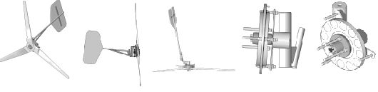
Pictured above the machine is about finished up, the alternator is assembled.

Here is a picture of the other side. There are two bridge rectifiers behind the Aluminum cover to rectify the 3 phase AC in Direct Current. The meter has a 6 amp scale. At this point, with the airgap between the magnet rotors taken up as tightly as possible, it produces 12.5 Volts DC at 38 rpm. The back magnet rotor has 3 jacking screws so that we can adjust the airgap, and allow the alternator to run faster if we need to, in hopes of matching the speed of the alternator to the optimal speed of the runner. Lots of adjustments on this machine!
Page 2: Hydro Electric machine with direct drive PM Alternator
So that's where we left off on Page 1 of this project. So far we've got about 3 days into it all! It's lot of fun doing this sort of thing.. even if it doesn't work!

It's amazing how we can fit a hydro project, a big wind turbine project, lots of tools, and 17 folks with instruments including a standup bass in half of my 10 X 50 trailer!

Back to work. We spent about 2 hours grinding rust off it, sprayed primer and paint over it. Probably not necessary, but it makes it look nice, which is especially important if it doesn't work!

Here it is all painted up! We'd intended to put a shroud over the alternator that would rotate with it, to keep water out of the bearing and off the electric components. We never found the right piece and ran out of patience with that, but we will add that later if it works well enough to warrent the effort.

Another shot of it assembled. We've not put the nozzel on it yet, it's in the back of the truck.

Pictured above you can see where we plan to put it. The 4" pipe comes from the bottom of the dam, again.. about 3' of head. Its a thoughtful arrangement. We're only taking a small portion of the water from the creek here. Up above the dam there is a bit of an island which splits the creek. Some of it feeds the dam, the rest of it flows round the side so as not to interrupt the creek.. fish can still go back and fourth, and if the creek is high, it won't have much affect on things.

This is Scott's old machine, which ran for 2 years even through the winter. Again, it was good for about 1 amp (12 watts) or so. It's a squirrel cage blower, belted up to an Ametek computer tape drive motor. To get an amp from it, the belt tension was very critical and required frequent adjustment. It was a good machine though! Hopefully what were doing here will be an improvement...

Here we've got the machine at the site, and are making adjustments. Again, just about everything is adjustable here! In the end, we got best results by feeding the water in at about 10 O'clock on the wheel, most of the water seems to exit at about 5 O'clock.

Here it is running along making about 2 amps (1.9 amps to be precise). We were hoping for at least 2.. but after lots of adjustments we simply couldn't beat 1.9! It's tricky to adjust! Every change we made to the alternator changed the best nozzel position. We could adust the airgap on the alternator, and we could change the wiring from Star to Delta. I definitley noticed higher efficiency in Star... it always produced slightly more power at the same rpm in Star with a wide airgap than it did in Delta with a narrower airgap. (the airgap is the distance between the magnet rotors and widening it reduces the flux through the coils allowing it to run faster) We left it in Star, with an airgap of about 1.25" (pretty wide!). So, it could be made at lower cost with smaller magnets, and a narrower airgap, or... it could be slightly more efficient with the same magnets, a narrower airgap, and coils made up of fewer windings and thicker wire. We may make this change at some point. As it is, it runs without a load at about 160 rpm, and loaded at about 110, producing 1.9 amps @ 12 volts.

Well, it was lots of fun and it seems to work reasonably well. We need a shroud over the alternator to keep the water off and a screen over the intake. One problem that I never thought of... the creek is full of magnetite sand! Even after a couple hours I could see a little building up on the magnets. It might payoff to have a screen, and lots of magnets at the intake to collect some of that before it gets to the wheel. A shroud over the alternator would also serve well to keep almost all the water out.