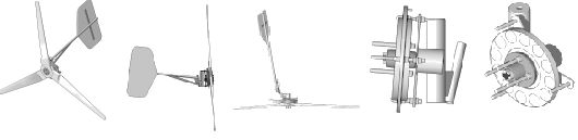
10' Wind Turbine construction, 3 phase Rectifier
Building the 3 phase Rectifier
The alternator you've built produces 3 phase alternating current. In order to charge batteries you need direct current. You can convert the alternating current into direct current by running it through an array of rectifiers (diodes).
Materials list
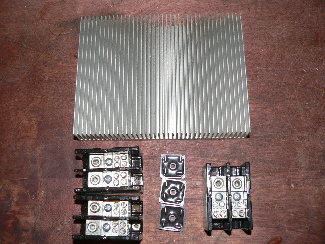
3 full wave bridge rectifiers, minimum 35 amp rating
1 Aluminum heat sink
Terminal blocks
Silicone heat sink compound
12 Spade connectors for 10 gage wire
A few feet of 10 gage wire

The full wave bridge rectifier has 4 leads. Two leads (on opposite corners) accept incoming alternating current, and the other two give Direct Current out. Sometimes all 4 leads are marked, but in most cases only the positive (+) DC lead is marked. Usually the positive lead will have a flat corner near it, and the spade is usually at 90 deg to all the other spades. Negative is on the opposite corner from Positive. The heat sink is simply a piece of finned Aluminum. They can be fairly expensive to buy, but they are easily salvaged from electronics. You'll find nice big ones on old car stereo power amplifiers, power inverters and lots of other places. We've used finned Aluminum cylinder heads from small engines as well. The heat sink draws heat off the rectifiers. There is approximately a 1.4 volt drop across the bridge rectifier. You can multiply that number by the current flowing through them to figure out how much heat will be generated in the rectifiers. For example - if the wind turbine is producing 10 amps then 14 watts will be wasted as heat at the rectifiers. Without a heat sink, the heat will build up in the rectifiers and they'll over heat and fail. The lower the system voltage, the higher the current through the rectifiers will be so a larger heat sink is required. In 12 volt systems about 10% of the energy produced by the wind turbine is wasted in heat and a large heat sink is required (if the wind turbine is producing 100 amps then your rectifier is a 140 watt heater!). This is one of many reasons to avoid lower voltage systems. It's a good idea when you finish your homebrew wind turbine system to watch the rectifiers closely, see how hot they get in high winds. If it seems to be getting hot, rebuild the rectifiers on a larger heat sink.

Pictured above is the schematic of the system. You need 3 rectifiers and they should be rated for the full current you expect from the wind turbine. In reality, each rectifier must handle about 2/3 of the total current but if you rate them for at least (preferably a bit more) the full current that your wind turbine will ever produce then you have a bit of a safety factor. For this 10' diameter machine figure maximum output to be around 1200 watts. At 48 Volts that would be about 30 amps so you can use 3 35 amp bridge rectifiers safely. At lower voltages you'll need heavier rectifiers - or - you can wire up multiple rectifiers in parallel. The schematic above shows it fairly clearly. Each line from the wind turbine will connect to both AC leads of it's own bridge rectifier. The DC leads of the three rectifiers are in parallel and can wire to the battery. The schematic also shows a 'kill switch' and sometimes the rectifier block is a nice place to mount this. A DPST switch will serve to stop the wind turbine - to do this you need to wire it up such that it will short all three of the AC leads together when the switch is closed, and leave them all open when the switch is open.
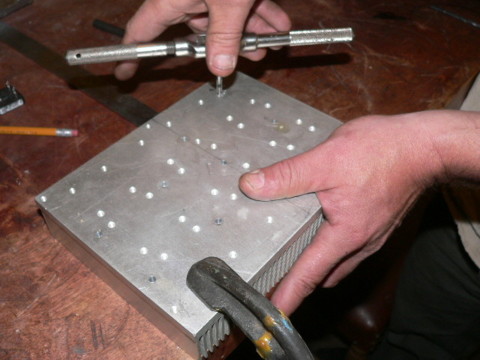
The first step is to pick locations on your heat sink for the rectifiers and the terminal blocks. Drill holes and tap them, usually 10-24tpi screws are appropriate for mounting the rectifiers.
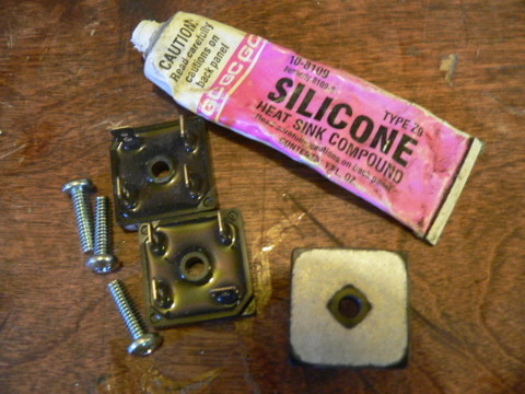
Put a bit of silicone heat sink compound on the bottom of each rectifier before you screw it down. It's a sort of grease that helps the heat sink draw heat off the rectifier.
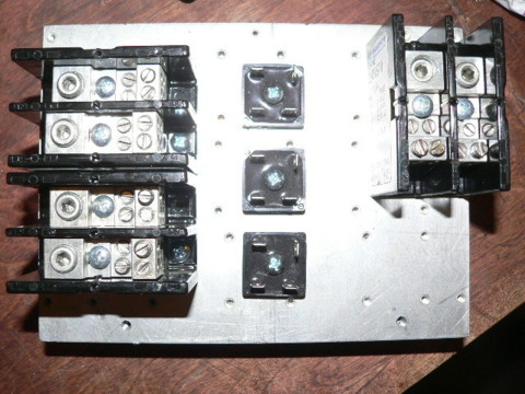
Mount the rectifiers and the terminal blocks to the heat sink. The terminal blocks in the picture are larger than necessary but that sort of thing is typical when you're salvaging parts from other equipment. Better to have things oversized than undersized!
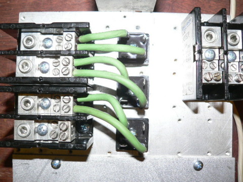
In the picture above the AC leads of all 3 rectifiers are connected to the 3 terminal blocks which will connect to the wind turbine. Now we have only to connect all the (+) leads together and bring them to the (+) terminal block, and do the same with the (-) leads.
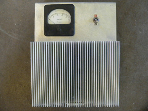
Pictured above is a finished rectifier. The one in the picture also has an ammeter in series with the negative DC line so that the output from the wind turbine can be monitored, and a kill switch (to stop the wind turbine) wired into the AC end. It's nice to get all the components in one clean unit like this. Also there should be some kind of bracket (or box) so that the rectifier can be mounted to a wall. The rectifier should be mounted so that the heat sink is vertical, (not laying flat) and the fins should run vertical - not horizontal so that air flows up between them more efficiently (this improves their ability to transfer heat to the air).