Induction motors are commonplace, you'll find them on tools, furnaces, blowers...etc. It is possible to convert them into effective brushless low rpm alternators by installing permanent magnets in the armature. We have performed experiments installing surplus computer hard drive magnets into the armatures. Undoubtedly, a "surplus" magnet is probably not optimized for the application, but the results have still been promising and we think it might be a cheap, quick, and practical approach to building a low rpm alternator. Unless extremely creative, one would probably need to have, or find somebody who does have, a metal lathe...that makes it a half hour project.
Para Español, traducción de Julio Andrade.
NOTE -- We've stopped experimenting with these conversions. They work, but the windings of the motors are just not made for producing lots of power. The resistance is way too high, which makes them VERY inefficient once they reach higher speeds. They also cog, which causes slow startup. We've found that it's the same amount of work to build an efficient alternator from scratch as it is to convert an induction motor, and the home-made alternators perform MUCH better. You can see some of our latest, most powerful, and most efficient from-scratch PM alternators on our Wind pages at left.
Magnets
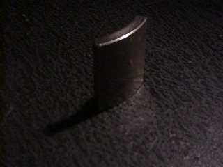 Pictured above are the magnets we've used, though undoubtedly any small magnets could be arranged to work reasonably well. The magnets we used are rectangular, and arched such that 8 of them fit to form a ring approx. 3 3/4" diameter(pictured above), which seems to be a fairly good match for induction motors from 1/2 hp to 2 hp. The magnets come out of a computer hard drive, ours are surplus, and are available from our products page. The come magnetized with either the North or South pole on the concave surface. These are NdFeB(Neodymium Iron Boron) magnets, of extremely high grade - much stronger than normal ceramic or AlNiCo magnets.
UPDATE -- These magnets were surplus, and they have SOLD OUT. We cannot get any more. We do have some rectangular block magnets that should do the trick, and still fit inside the armature....you'll just have to turn out the slot differently.
Pictured above are the magnets we've used, though undoubtedly any small magnets could be arranged to work reasonably well. The magnets we used are rectangular, and arched such that 8 of them fit to form a ring approx. 3 3/4" diameter(pictured above), which seems to be a fairly good match for induction motors from 1/2 hp to 2 hp. The magnets come out of a computer hard drive, ours are surplus, and are available from our products page. The come magnetized with either the North or South pole on the concave surface. These are NdFeB(Neodymium Iron Boron) magnets, of extremely high grade - much stronger than normal ceramic or AlNiCo magnets.
UPDATE -- These magnets were surplus, and they have SOLD OUT. We cannot get any more. We do have some rectangular block magnets that should do the trick, and still fit inside the armature....you'll just have to turn out the slot differently.
The Armature
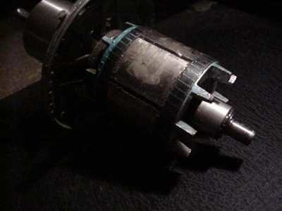
The armature will need to have a slot cut, to accept the magnets. We think they should press in fairly tightly, and then glued applied(epoxy is probably best). Odds are the curvature of the magnets won't match up perfectly with the diameter of the armature, so the slot needs to be deep enough so that the highest point of the magnets is flush with the surface of the amateur. In the armature above, there are 6 magnets used. We used feeler guages to even up the gap between the magnets. Undoubtedly one could drill out the armature to accept disc magnets, but disc magnets are not ideal, and some performance would be compromised. Of course, the number of magnets used depends upon the number of poles in the motor. A 3600 rpm motor would have 2 poles, 1800 rpm 4 poles, and 1200 6 poles. Voltage is dependent upon the speed at which the magnetic field changes, so...the more poles, the better candidate the motor would be for a low rpm alternator. The lower the rated speed of the motor, the better it will work at low rpm. In our tests, we always used the same number of magnets as poles, except in a 2 horsepower motor, which had 4 poles. In that motor we installed 8 magnets, but in sets of two such that there were 2 North and two South poles on the armature.
Results...
The first motor we tested was a 1/2 hp furnace blower motor, rated at 7 amps and 1050 rpm. It had 6 poles and we installed 6 magnets in the armature, equally spaced. It cogs(when the magnetic field locks in with the slots in the motor stator) enough such that it is difficult to turn the shaft of the motor. It hits charging voltage(12 volts) at approx. 80 rpm! At 400 rpm, it will charge 12 volt batteries at over 10 amps. We tested this with a wind generator propellor - See our wind pages at left; Basically, it worked fairly well, but he wind speed had to hit about 10 mph before the propellor would start turning. Once it started turning...it kept spinning and generated well. We also hooked this one up to a bike- it would easily put 10 amps into the battery with pedal power. I suspect this one would probably peak at 15-20 amps, but it becomes inefficient after about 10. This could be changed if one could make a regulator which would take the coils in the motor(alternator) out of series and put them in parallel at a certain rpm. Another drawback of this motor...it was a fairly cheap furnace blower motor, with bronze bushings, it might last longer with higher quality bearings.
The second motor was a 2 hp single phase 1800 rpm, rated at 15 amps. In this motor we installed 8 magnets. Oddly, these computer hard drive magnets just happen to be a perfect fit, there are no gaps, and no overlap - the diameter of the ring is exactly that of the armature. The magnets on this motor are in sets of 2, so...we put 2 magnets with North up, then 2 magnets with South up...etc, so that there are 4 magnetic poles on the armature. This alternator doesn't cog nearly as bad as the first one, and would certainly work well on most windmills. It doesn't reach charging voltage until about 150 rpm, but...at 400 rpm it charges my batteries at over 15 amps, and would probably be efficient up to 20-30 amps.
Both of these test alternators become very difficult to turn by hand if the wires are shorted...even a couple of rpm by hand will produce a very noticeable spark at the leads. This might be an excellent alternative, considering the difficulty and labor required in making an alternator from scratch. Considering just how slow these alternators are charging, they may have the most potentual of any low rpm alternator we have yet to run across. We'd like to know what other folks have done in this area, so please send us an email if you have any ideas/experience.