How to convert a seeley into a robust turbine unit
Well the dust had settled on the AWP debarkle, and it was time to ponder the good points of the rotary drum design, which the AWP epitomizes. I liked the simplicity and robust construction, the high voltage system and the transformer coupling to the batteries..... I was hooked.
Upon chatting to Bryan and Bruce in the IRC, I learned that the Seeley air conditioning motors which had appeared some time earlier on both fieldlines and backshed.com could be obtained locally (In Australia) for less than $50.00 AUD..........I had to have one........
So A few phone calls later one was on the way from Dennis.
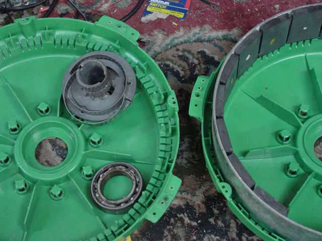
The post office called and I scuttled into town on a Friday afternoon and picked it up. Well you know the story, couldn't get it out of the box quick enough and soon it stood on the floor in pieces.
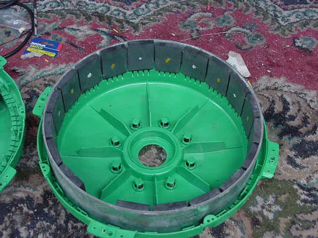
It was at this point that I decided that the motor had no future as a wind genny, unless we throw all of it out but keep the stator...... so into the pile of junk it went, but the stator was a thing of beauty and simplicity, and was destined to fly.... just had that feel.
Getting the idea from “gee it's a nice stator” to a working device was going to be a bit problematic. A pipe the right size could be easily cut and fashioned into a drum. The only thing wrong with this idea was no pipe on this island that size...... Hmmmm
I could bend some 6”flat steel into a circle, but had neither steel or curve bender for 1/4” steel... in fact nothing that would contemplate such a thing. The other minor problem was that I had no 6” x 1/4” steel either.
I decided that in the spirit of the DIY mill, I would make it without recourse to any equipment I couldn't reasonably expect others to have access to...... this limits things greatly, but I felt it was do-able. I also wanted to crack the adjustable air-gap for a rotary genny nemesis.
So what to do next.....
What I did have was some pole braces 2”x1/4” flat that is used to hold the cross arms on the power poles over here. I also had some 350mmx 8mm steel disks with the hole pattern of a trailer stub. I had the stubs and hubs for these disks as I will be using these at a later date to build the axial mill. Everyone else seems to find these for their axial fluxes as well, so I used them with a clear conscience.
I spot welded three of the braces together to get my 6” wide steel flat.
I cut over halfway through the steel at the 54mm marks for 11 cuts.
This allows me to bend each segment at 18degrees of arc by hand.
Here
are the strips of 2" x 1/4" braces, the cuts required (in
a single one for test) and the final drum
When you finish the bending, you end up with a semi-circle of the correct diameter, with 54mmx75mm flat plate steel for the 25mm thick magnets to sit flush against. Two of these and we have the makings of an adjustable drum. I liked the idea of the flats to place the magnets on,because I will lose a little bit of flux through the cuts (even though they almost meet each other when bent) but gain a bit by having the magnets flat to the backing. On a circular drum they would stand 1.5mm or so proud of the radius at the center of the magnet.... probably come out about even in the flux stakes.
New
magnet block bottom left, original bottom right
I had 100 magnets (ferrite's) for a hundred dollars, for which I had no idea what to use them on..no good on an axial flux, and I have the neo's for that project, so this project seems ideal for these mags. They are 25x25x40mm. I only had to stick three together to get the 25x40x75mm mag blocks I wanted.
This proved more difficult than I had previously supposed. They repel remarkably well, and when your up to your armpits in 5 min epoxy, it is a little difficult to handle them all as they scuttle around the desk with sticky epoxy on them. I eventually did only 1 mag block at a time and clamped it, and moved onto the next. It was slow, and there are probably better ways, but this finally got 60 magnets masquerading as 20 big magnets.
It quickly came to my attention that 20 big magnets can zip around the table even better than the little ones could and from a longer distance too.
It came as no surprise that I had a few magnet chips left on the desk when all this was over which when mixed with the blobs of 5 min epoxy made for a mess to clean up.... sigh, glad they weren't neo's
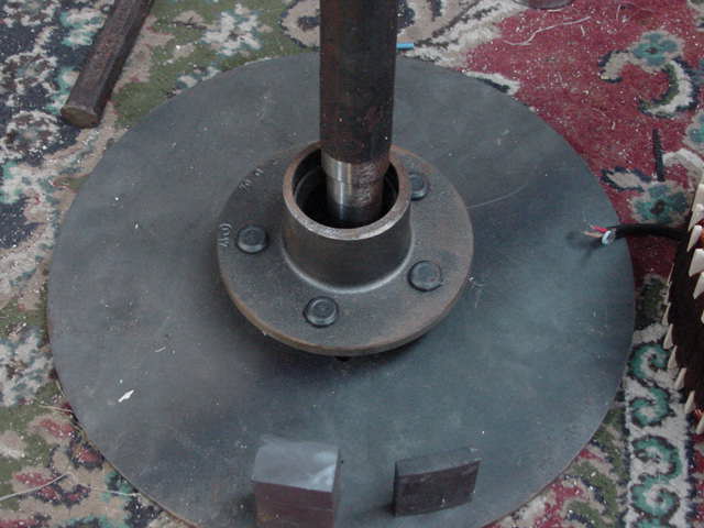
The shaft for the project is a standard 1 1/2” shaft with the machining to match the hub. The rotor disk I had made for the axial flux ,will be used for the drum face. (I have plenty more of these)
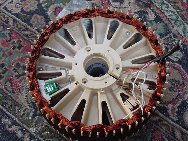
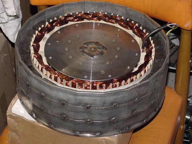
The original Seeley is rated for 1500W, and the wire is a good size to support the expected 3-6A per phase I was hoping for. The stator is interesting in that instead of a laminated stator, it is a plastic molded form. It has a layer of steel wire around the periphery, then a plastic insulation layer, and then the coils are wound over the top of this. The upshot of this is of course, wood, resin cast, almost any non-conductive material you are happy working with can be used to create a stator of any size we wish. This will have to be done in the near future, as we can now make the stator and the drum any size we please. In this instance, WXYZSCIENCE's round resin former springs to mind ( http://www.fieldlines.com/story/2006/10/8/25249/8931) as a useful system perhaps over a wooden former. In this case we end up with 60 coils of around 38 turns ...20 coils of .8mm wire per phase. Coil width is about the 40mm of the magnets I am using, and cover three stator slots. The coils are overlaid.
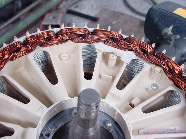
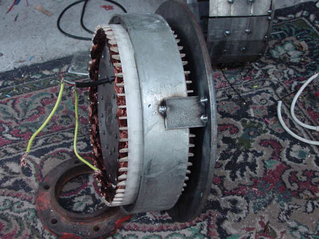
This
shot shows the wire backing that is under the stators wiring, giving
it it's steel backing. Using this bunch of magnets, the iron loss is
noticeable. There is no cogging obviously, but the iron loss will
hold the blades back more than an axial.
I used the lathe to make a rear mount to hold the axle stub, but it is not necessary if your careful and have some other flat steel at hand. It doesn't need to be round, but the stub does need to be welded perpendicular to the back plate(whatever shape you make it).

Before
welding the stub in the stator back. It does not need to be round.
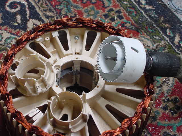
The stator needs to be bored out to allow the trailer stub and the back of the hub casting to freely rotate within it. I used two hole saws (1 in side the other) to bore out a large hole that would allow the trailer hub to rotate freely within the stator. The smaller (2”) hole saw fits nicely in the original stator hole and this centers the larger hole saw to cut out the large hole required for clearance.

The
tricky bit is to mount the stator to the backplate. The stator is a
spider web of plastic molding, and difficult to get a good fix to. I
temporarily used 12 self tappers to hold it in place until I put in
12 larger ¼ metal thread screws to clamp it securely to the
backplate.
![]()
This
is the stator with 12 self tappers to hold it in position before the
big screws go in (around the perimeter of the round plate.)
Once that is done, it's a simple matter of wrapping some masking tape on the stator of a thickness you want the air gap. (1/16th inch or greater perhaps). We then place the stator on the rotor plate (with bearings and rotate to see how close we were on the backplate to stator centering. Fiddle with it until it is centered when you turn it. When the stator runs true, and your satisfied that there is no wobble when you spin the stator, and there is no side to side business going on when you turn it, then tighten it up with whatever system you have used to mount the stator to the backplate (in my case 12 self tappers and 12 metal threads .. not shown).
Once thats done you simply place the magnets around the stator. At this point, things seem to be going fairly well. I machined in a groove to take the magnets, but once I used the masking tape as a gap thickness device, they are not necessary and the lathe work was a waste of time.
Here we see the step I machined for the magnet spacing distance from the stator. I didn't use it in the finish as the masking tape makes it idiot proof and requires no lathe... win win.
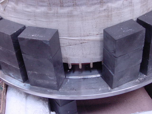
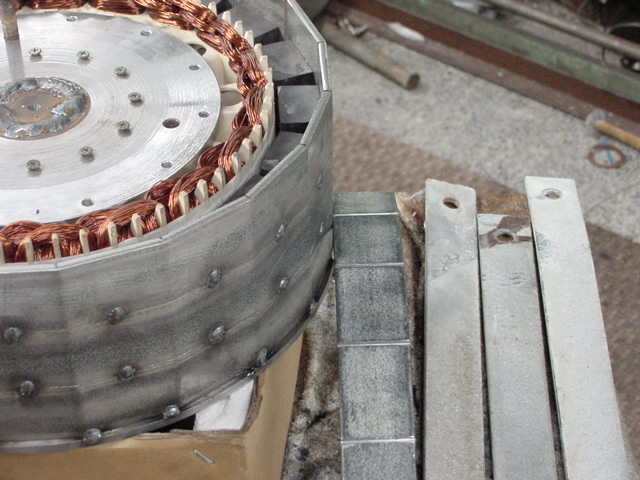
The segmented bands can now be placed around the magnets, and presto, you have a custom diameter drum. If you cut the bands more than halfway through, you should be able to bend them (pulling the appropriate face) into shape that exactly matches your magnet path. Spot weld to the front disk... and it's all over bar the shouting.
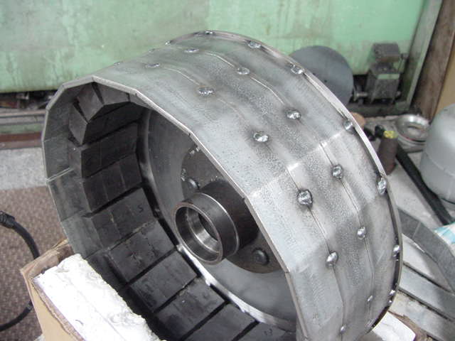
Strips
and test bend in the background. Mags not glued yet.
Once your happy with the clearance, and don't wish to change the air gap (you can test it for your iron loss and voltage per rpm at this stage. If you want more air gap, cut the spots, wind on more masking tape and re spot it. This manufacture is both simple, easy, and is the only way I know that you can at last change the air gap easily in a rotary format.
If you are happy with it now, weld it up for real, although a few more spot welds will hold it as there is very little stress on these welds. The circular shape helps self support it, and 20 spot welds all the way around seems plenty strong until testing is over.
I have a gap if 3/16th inch between the two halve of the drum walls where they meet each half, which will be filled when I'm fully satisfied with the air gap. I know we lose a little flux here, but it won't be significant, and will be welded when it is tested with the blades.
Armed with my new radial flux drum turbine, it was time to test it.
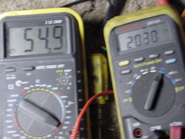
Hooking up an ac meter to one star phase and a frequency meter gave me the figure of 54volts at 120 rpm(20hz) 15R resistance in star
(7R5 per phase winding) this should give about 2kw@240rpm.... not bad for ferrite's. with no cogging less than AUD $200.00 invested in this thing.
With 20 poles, thats 40hz which is very transformable.(240rpm) It will drive a 240v step-down transformer array. This will match the impedance ideally to the windings (which were 240v dc brush less coils) I don't think it would be much good driving a low voltage battery pack without transforming.
As an interesting test, I hooked the output up to a transformer and measured the throughput, after about 15hz, the transformer behaved fairly well, and at 20-25hz, it seemed to perform almost as well as at 50 hz...... interesting.
I feel that the drum style alternator is not given nearly as much credit as it should, and is easy to build with virtually no tools and an off the shelf trailer hub set.
I consider that this turbine will give a reasonable account of itself
It doesn't take a lot of imagination to see that fashioning the stator out of wood, or resin is a distinct possibility.
Stator ...............$45.00
Magnets ...........$60.00 ($1.00 each for 60 mags to make 20 mags)
Trailer Hub........$65.00 (inc bearings and stub and nuts and split pin and dust cap and seals.)
Front disk..........$20.00
Rear stator disk.$04.00
Drum strips.......$free
Tools......hacksaw and welder to weld the stub to the stator back plate, and the spot welds on the drum. (the lathe work I did was not necessary)
So for about $200, we have a decent power plant to play with. It is tough, cheap, and I can't find a reason to build my axial flux now. It makes no sense anymore.
These things are absolutely doable. I have a lot of money tied up in stuff to do an axial, but on a dollar for dollar/watt basis, the axials look like a miserable choice. It is only the lower winds that the axial would do any better (iron loss issue with all steel cored designs getting out of stall.) Might stick my 100 50x12 N45 neo's on ebay, and buy the cheap and nasty Ferrite. (5 of these Neos, will buy 60 of these ferrites) Cheaper mags, easy to work with and loads of power in this configuration. The next one I make will be 30 poles (to get the Freq up further) and maybe a 20” drum. Making the drums like this is child's play and cheap as dirt.
Temperature of the stator will be of interest with further testing, but using transformers to match the load should sort this out well. (3x 1kw microwave transformers rewound and losing the welded sides should do nicely. (the welds down the sides create losses from eddy currents so in continuous operation they heat up unnecessarily... jimovnz seems to have beaten this somehow he tells me)
If you want to do a version in 20 minutes, just use the seeley magnet ring, weld on a few bits of off-cut to the ring and weld to the front plate. ...make the rear stator plate and here you have a device of roughly half the output of the one above..... like this...
I
built this one just to test the original output figures they are
almost exactly half the bigger magnet one. The air gap is closer than
the larger mag one, and the iron loss is surprisingly small also.
25v@120rpm approx 15 ohms per star
phase. 115W in theory. Or at 360rpm it would appear to make 1kw. ((V
xV)/R) This config with it's very low iron loss would start to
challenge the axial for freewheeling , and for around $120.00. it's
not that bad really.
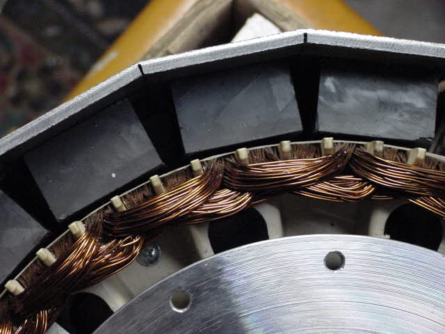
Close
up of the slits and mag clearance and the flats behind the mags
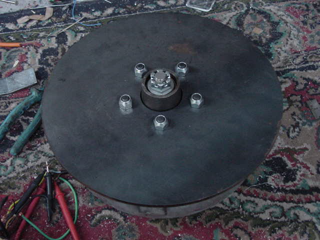
And ready to mount on a yaw bearing. (the 12 main bolts are not installed as yet (got no bolts here)
The three M10 holes are to take the mounting studs from the yaw mount
Front without the dust cap (a variable pitch prop mount is being developed for the direct fit to the front 5 wheel studs) (this is the front of the 20min conversion using the original magnet ring)
Well it was fun anyway.
Any questions?
..............oztules