African Wind Power Review.....
Well, I got the call...How would you like to help me rescue the AWP... again.
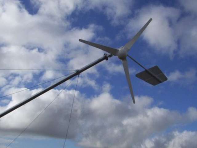
The African Wind Power turbine is a remarkably well designed and very poorly implemented wind turbine. The designer can be justly proud of designing an excellent machine, but has been very badly let down by the manufactures of this machine. So this is coming down.
First off last year the thing wouldn't go together properly because shoddy hole placement ... someone had put the drill template back to front I guess (the tail had to go on backwards to match the holes... had to be re drilled). Next the alternator wouldn't bolt up to the vaw housing as the 4 bolts that hold the stator to the bearing housing were too long and interfered with the weather shield on the back of the turbine... wouldn't turn..... Both these problems were simple to fix but should not have been there in the first place.
Once the machine was flying, it produced reasonable output in lightish winds..... very nice, but as soon as heavier winds were encountered, the furling system went into overdrive, and next to no output was recorded when the wind blew... not really the general idea of a wind machine..
After advice was sought and very expertly given by Hugh Piggott, we cut off the tail mount tabs, and re welded then to a different angle, and all was well. Output now was a very respectable 1Kw plus all day every day. This design is truly excellent. It puts out it's 1100 watts in seemingly light breeze and accounts well in higher winds as well (now anyhow). It exceeds 24kwh per day on most days, and spends a lot of it's time dumping. The batt bank is only 24kwh (48v) The house runs electric hot water, a washing machine that “she who must be obeyed” insists on using on near boiling water (yes the one that heats it's own) and all the mod cons available. It has 1kw solar bank as well. Like I said it dumps a lot of the time. It puts out a steady 20-24Amps at 50-60 volts all day..... yes the winds on the 40th parallel are pretty consistent.
Then there was the African Electronics.
This brings about a whole new world of quality control.
Here is the frequency controller box.
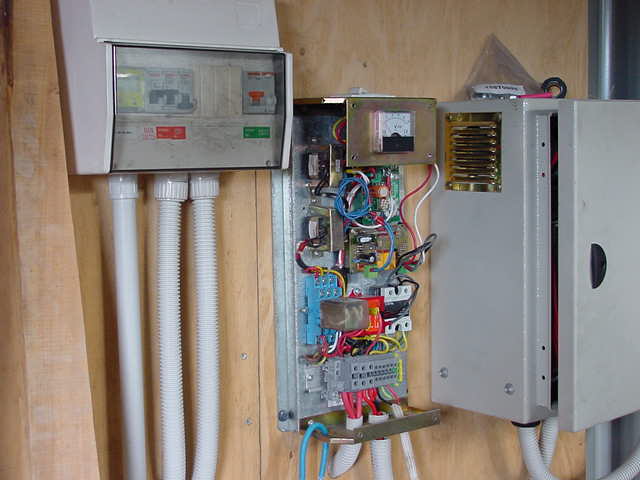
It measures the frequency from one of the two tiny step down transformers (the mill is nominally 240v..... 180-500+v really). The second transformer runs off a different phase and provides the drive to the over voltage relay (clear plastic box on blue connector pad) and the two solid state relays that turn on the HV line to the transformer (the third phase is hardwired to the transformer input.... you only need two relays then) The offshoot of this is that the small transformers output varies with mill speed ie they output from 0 to 20v or so.
Now, it derives its 240v for the input from the mill, transforms it to 12v, and measures the frequency with a microprocessor and outputs the results to two solid state relays. One 240v line is always connected to the power transformer (pictured)
![]()
and
the other two lines are supposed to be switched by the relays to put
the other two 240v inputs to the three phase power transformer, step
down to 48v, rectify and charge the batts via the dump controller and
the main inverter.
What really happened is that the bunnies putting it together, decided to use two solid state relays that had different turn on voltages.... one came alive at 4.5v and the second one which looked identical was alive at around 18v, but would cut in at perhaps 13v at a pinch .(but it's indicator led said it was latched at 4.5v as well so it said it was coming on line when in fact it wasn't yet..... till the voltage reached 13-14v)
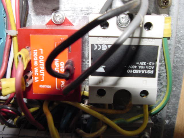
(There
were two of the white and black RS1A4SD10.... except one was 18-48v
not 4.5-32v... the red one is one i rebuilt to replace the RS1A4SD10
18-48v. It switches on at 3v.)
The effect of this difference was that the power transformer would run as single phase in light winds as the drive transformer could not provide enough drive to the second relay to latch... this made for very intriguing noises from the transformer and reduced low wind output. As the primary voltage increased, the voltage to relay no#2 pulled it on, and the transformer would run normally. The side effect and problem #2 was that the over voltage HV dump relay (>350v) was chattering.
Initially the system could only be run with the relay pulled out.
So I pulled the solid state relay apart, and rebuilt it's input sense, and got the trigger voltage down to 8v. This steadied the whole process and they switched on simultaneously (well almost) and this solved problem no. 2
Problem no.2 was that the over voltage sense was derived from a second small transformer cunningly wired across the primary that was being switched in by the higher voltage relay. The effect was that freewheel voltage from the second phase (not switched in by the solid state 18v relay) was telling the sense transformer that we were way over voltage (because of the higher voltage relay start time) and pulled in the over voltage dump.... this slowed the turbine, and stabilized the wild ac on the second phase....... the voltage drops and the over voltage relays drops out .... what this means is.... pyrotechnics in the triple gang over voltage dump relay which chattered like a machine gun and destroyed the contacts in no time. If it got through this stage (the wind gets stronger) it pulls in the second phase relay and thing stabilizes.
With all these interrelated faults it took a little time to figure out what was going on. To complicate matters, the leds on the solid state relays came on at the same time making me think they were engaging at the same time (which they weren't) and so on and so on.... looked like an intermittent fault in light winds.
I eventually built a solid state relay out of an old relay shell and opto isolators and triacs. This solved the problem for good.
So sloppy assembly of the frequency/ over voltage controller made a good system almost unusable. Once that was solved, the system put in a good year of very good output. The electronics now worked very well, so the design was vindicated, but the assembly was sloppy... wrong components that looked alike, and abysmal testing procedures. So a good stable design was let down by the assembler.
Alas, all good things come to an end.........a year or so on
Jamie called me and said his output had dropped, and the three phase transformer was making strange noises. We quickly deduced that we had lost a phase from the mill and decided that the slip rings were to blame.... time for the tower to come down.
So down it comes. The weather over here changes from sunny to complete cloud cover at incredible speed, and goes from sunny to wintry in 20 mins, so what looked like a nice day for it turned pretty cool pretty quick.
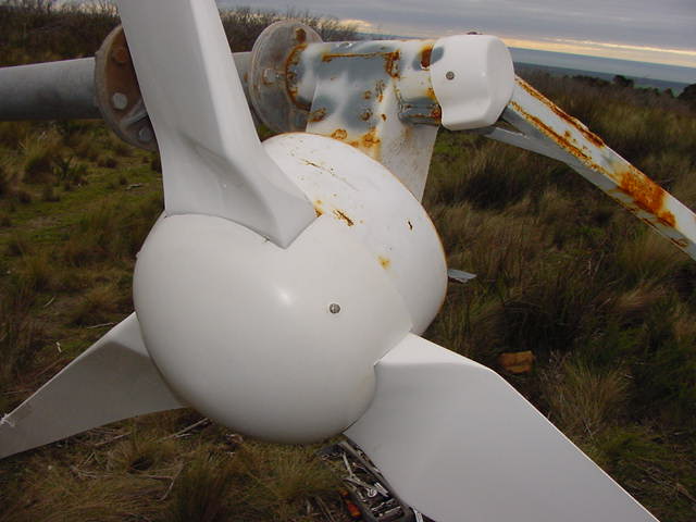
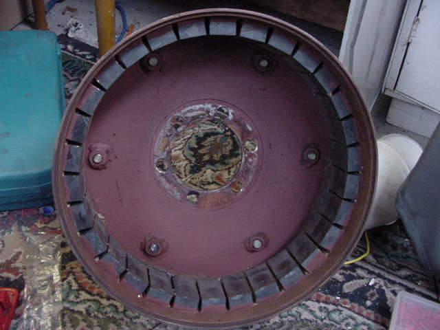
Here is the mill from the overhead posn.
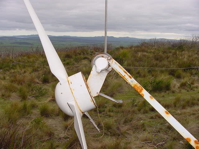
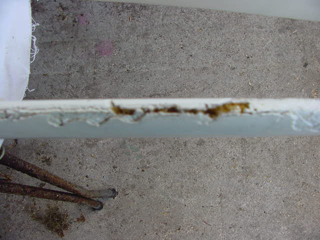
The marine environment hasn't been good to the African paint job, but structurally all appeared ok. The blades are a beautiful profile, and i would like to carve a set similar, I wouldn't even mind casting a set, but i wouldn't buy a set from these people as there was lots of gelcoat, but in some places that was all. In many places if you press too hard with a screwdriver or similar, you go straight through the gelcoat into large air cavities, and somewhere lurking within is the fibregalss. Some holes are ½ inch deep. The leading edges which are susceptible to some wear (although this is a slow turbine where tip speed is only about tsr5-7 times 25mph max (furls speed)) the leading edges have been badly damaged as the bubbles were more prevalent where tight corners in the mold allowed for bigger and better air bubbles to form.... consequently, when the blade did erode, it suddenly opened up large holes in the leading edge.......like this.
Jamie
took this photo... and the camera even has anti shudder and auto
focus a ten X optical zoom a 20 X digital zoom and can macro down to
13/16th of an inch... I don't know how he managed this
shot. (Sony FD95) (Actually, I think the camera was looking at the
floor, as it's profile is slightly meatier than the blade edge... but
I'll blame him anyhow) The leading edges also had tape on them to
help mitigate this destruction... it was supposed to be good stuff.
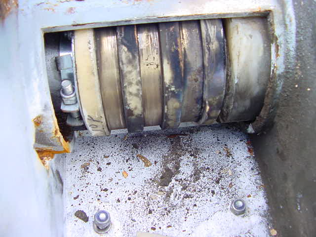
And one from the side.
This is the cause for concern..... slip rings are toast. One ring copped the worst of the abuse and the flame from the interaction was enough to cause complete destruction of the brush spring itself... which was thick spring steel. Must have been a little spectacular there for a while.
And the brushes are not that flash either
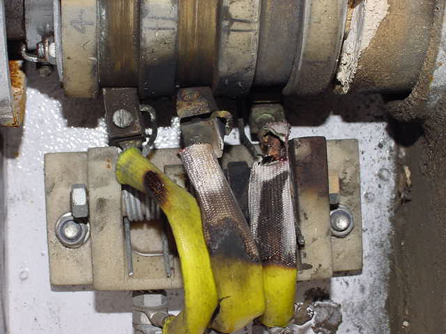
The
spring holder on the center brush is vaporised, and the one beside it
is not that flash either. There was some serious goings on occurring
in here.
But there are more disasters in store for us yet.
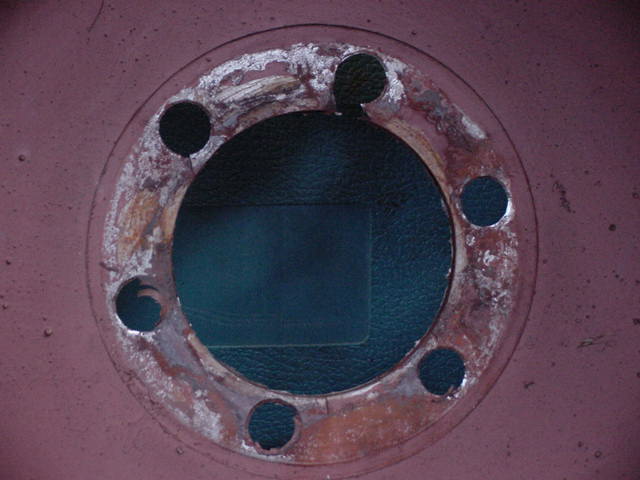
The lower yaw bearing is made from plastic and had gone ovoid, changing the brush positions and allowing them to collide with the plastic separation rings and ultimately with each other.
The
ovoid bearing allowed the yaw head to move considerably, and the
brushes couldn't track the slip rings. The retaining ring at the top
bearing was then under duress and popped out and the head had
vertical movement as well....... bye bye brushes.
Heres a look at the clearance: about a quarter of an inch slop.
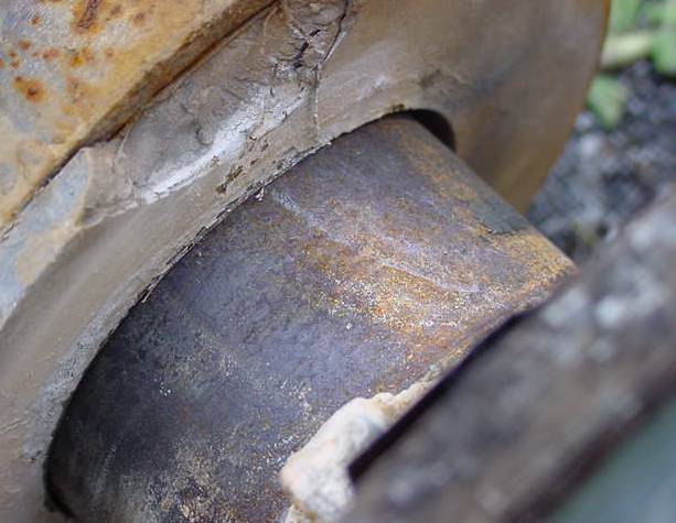
At
this point I was starting to think that the inside of the alternator
might have some toasty bits inside as well, because so far blackened
destruction seemed to be the order of the day. So it was with some
trepidation we opened up the housing to peer inside at the expected
carnage.....
For those of us worried about whether the coils would fry with this abuse... look at these picks
And for the disbelievers ... (me amongst them)
No damage to the coils was apparent... they were perfect. So robust design and iron stator may have saved the day. ... In truth, there was probably more arcing than direct shorting, so maybe an axial epoxy stator mill would have been perfectly ok as well. The mill still put out 800W with all this damage to the brush and slip rings. (about 14-18A at around the 58v mark into the batteries) Still, for the brush springs to have fused together whilst driving the load, there would have been some stress, but none showing here.
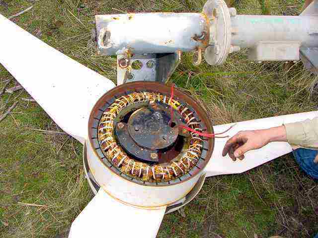
For the motor conversion people, here is the stator in all it's glory

Notice
the skew on the stator plates. The is no...... I repeat no cogging at
all ... i mean none. Once again, very good design.
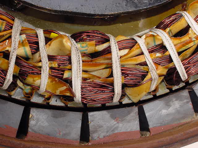
A closer look
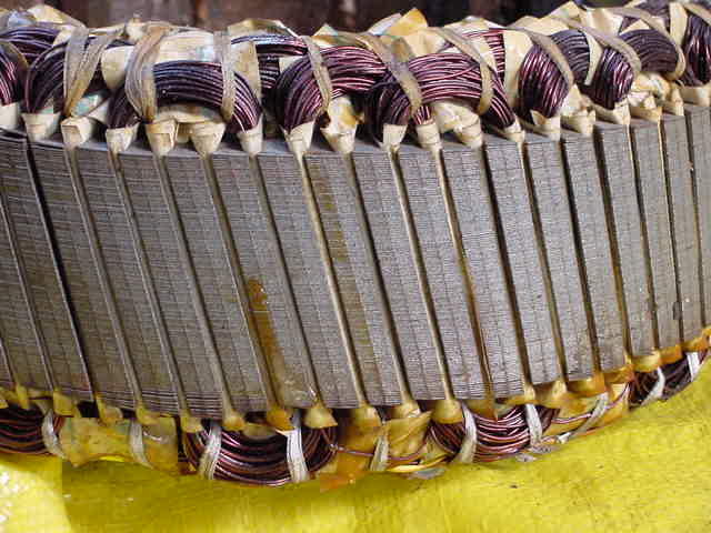
I
think this supports Zubbly's skewed stack idea nicely. It has 90
slots 30 magnets and 90 coils. Coil span is 3, magnet span is 3 wire
diam =0.8mm
Those ferrite magnets wouldn't pull polly off her perch compared to the neo's currently being used in the axial s, but they work remarkably well, and are very safe to work with. No pullers required here, the weight of the stator allows you to pull the rotor drum straight off, leaving the stator sitting on the floor.... I love it. The ferrite's are about 75mm by 25mm by 32mm.... just a guess . I didn't measure them as I had other things to ponder..... has she made dinner yet etc.
Whilst
you may think that looks nice, the manufacturing quality is witnessed
here again
Someone
had trouble drilling the hole and chamfering it successfully...
sloppy manufacturing again. They tore out two holes in fact not just
the one at the top, if you remove the loose paint on the top left, it
actually breaks out into the inner hole as does the top one. It's a
tribute to the design that with all this, the thing still works very
very well.
The next problem was the bearings, when we put the thing up originally, there was slight cogging, We figured it was from the magnet - stator interaction, but it turns out that the shaft was machined to large, and the bearings were forced onto it making the bearings bind and crunch...we thought it was cog but no. It lasted for nearly a year with the crunchy bearings, but now they were sick enough to notice.... very sick in fact. However with this design, it didn't effect the performance or the stator as it would on an axial.(on an axial flux as built here, bearing slop of this magnitude would have killed the stator and magnets i suspect)
I reground the shaft to better tolerance, and with new bearings there is no cog of any sort, bearing or magnetic.... here's the old shaft... the bearings were history and very crunchy. They were 6208 and 6209 easily over kill for this application..... except if you force them onto an oversize shaft.
![]()
She
was a pretty rough machine job by the manufactures, but it sorta
worked... which is about the same as their quality control.... sorta,
and I forgot to take picks of the cleaned up version, but now it's
good.
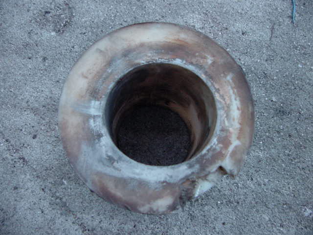
In the background you can see the slip ring assy partly rebuilt. Just to complete the picture, here is the bearing housing... had to clean out the undercoat from the seats, and this thickness didn't help the tolerance... it was damn good undercoat.
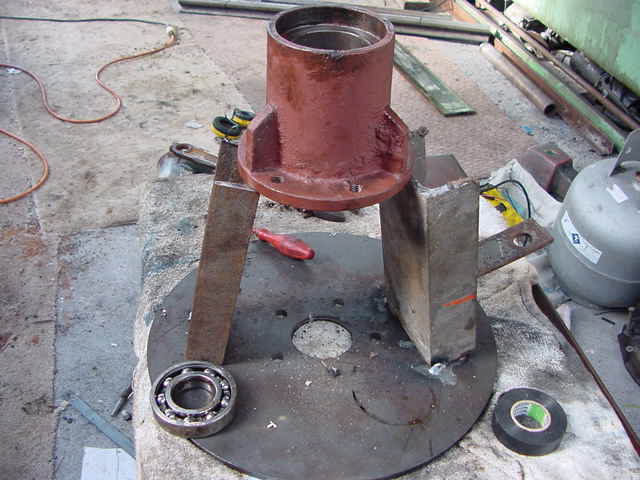
You'll
notice the channel under the housing......it was required so I could
press the stuck shaft out of the housing with a 40ton press. The 5
ton hydraulic puller wouldn't budge the bearings out..... just a
little tight. One of my axial plates was temporarily sacrificed....
one day it will grow into a wind turbine... more on that later.
The next exciting episode where Captain Turbine is suspended over a pit of alligators on a rope set on fire is coming soon..... note the suspense I'm injecting into this dull posting.
The next post will deal with fixing the problems on a remote island, and getting the thing back together.
Well thats it for part one if you suffered through that and want more...... we'll move on to part two.