African Wind Power... the fix.......
Well the time had come to tackle the other problems, the electrics were fine now.
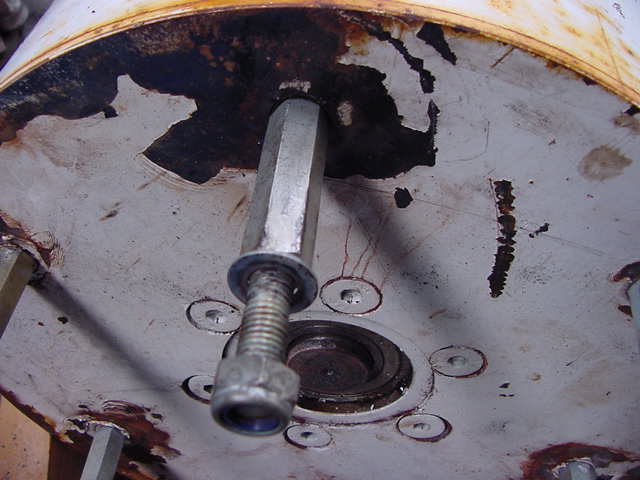
The first cab of the rank was to fix the broken stud that holds one of the props on. The stud had broken inside the threads machined into the mag drum face. This was a simple matter of using an easy-out (which I don't own) or a job for the trusty Mig Welder. First coat a fine layer of grease on the exposed threads in the hole, line up the mig nozzle and fire bursts of weld at the center at fairly high power. I slowly build up the broken bolt until it starts to protrude above the drum face. The grease stops the weld from adhering to the threads. Then grab the protruding bit with the vice-grips and undo. This takes some practice if working on small stud size, but with experience is a doddle. The heat breaks down the loctite and or rust, and this makes even the stiffest stud come out. Sadly I didn't take pics of this process, and forgot until I had locked the rebuilt stud back in. The broken prop stud was simply put in the lathe, machined back to the hex part, drilled and tapped , and a 12mm bolt sacrificed its threaded part to both screw into the hex and the drum face.
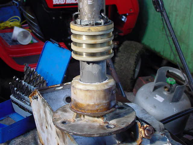
Next onto the ovoid yaw bearing. After a quick ponder and scratching around for some steel, a 2” water pipe joiner was found and machined down to the size of the yaw shaft. The clearance was kept down to .006” Not too tight, not too sloppy. The old ovoid bearing was then machined to fit the new inner sleeve. As can bee seen below, there is a chunk taken out of the collar. That was a crude attempt to get the old bearing out of the yaw tube... which failed miserably. We had to release the sliprings, pull out the wires, and slide the yaw post out of the middle.... and bash the begeezes out of the yaw bearing from the inside if the yaw tube. It came out kicking and screaming, but it came out.
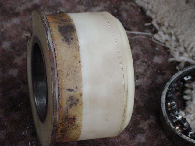
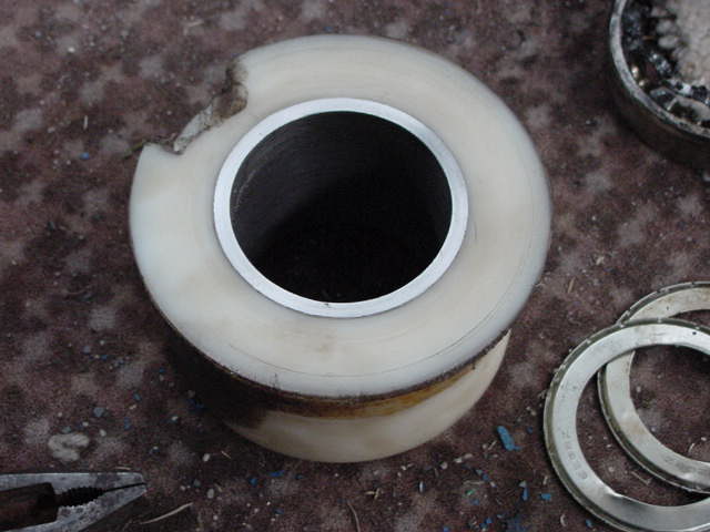
The yaw bearing was 2” longer than this, but didn't contact the yaw tube.... and it happened to be the same size roughly as the slip ring spacers..... so thats where the extra 2” went. Some plastic was skimmed off the last 3” to give a more useful fit into the yaw tube, and so next time we can get it out. Yes next time, coz this setup will only last a year or two, and we will build a new yaw shaft and bearing sleeve out of better materials probably stainless steel with grease seals.. then it should last long term.... but thats not now. Here it is from the top
So thats the yaw taken care of, now it's only the slip rings.
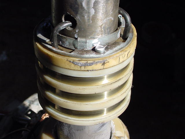
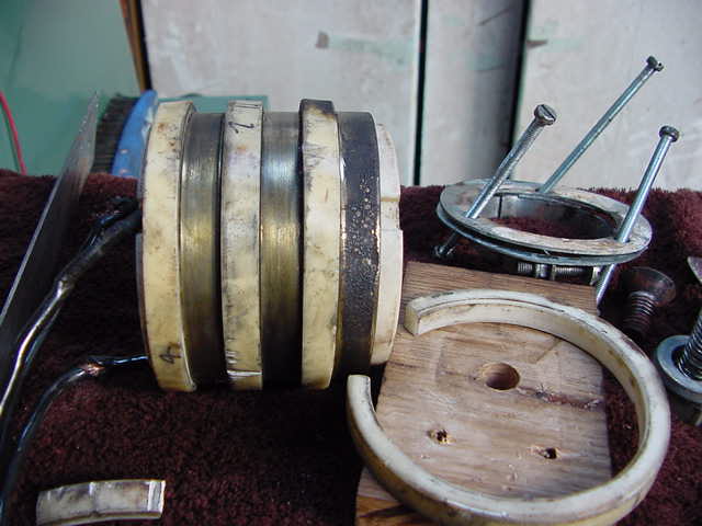
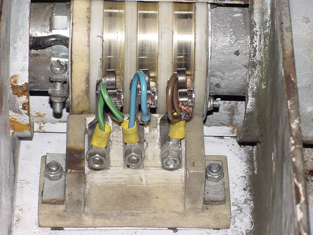
As mentioned earlier, the new slipring spacers were made from excess yaw bearing material. Here's some of the old rings and spacers
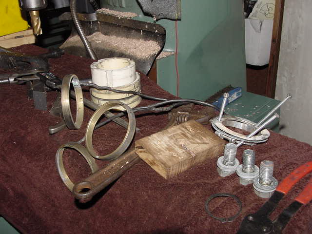
It also shows the 2 end plates with the retainer screws as well. The white former behind the rings is the slipring sleeve that holds the rings, and spacers. It also channels each phase wire out the ends and clamps to the yaw shaft.
When machined up and assembled on the shaft it looks like this
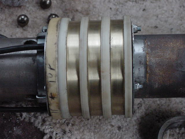
The
balls in the background came from the bearing which fell apart under
the 40ton press. They were tight. You'll notice the spacers are not
the same. Their spacers didn't match up to their brush housing
widths. So I made the spacers so they would match the brush
housing.... less chance for binding with the brushes. The old brushes
had all weird angles from being off center. Now we can just slide it
along the shaft to match the new brush housing. The oldish looking
end pack is how far out the spacing was. It was still needed to take
up the extra space left behind from the new thinner spacers.
Here are the old ones from part 1. note the alignment of brush to slipring.
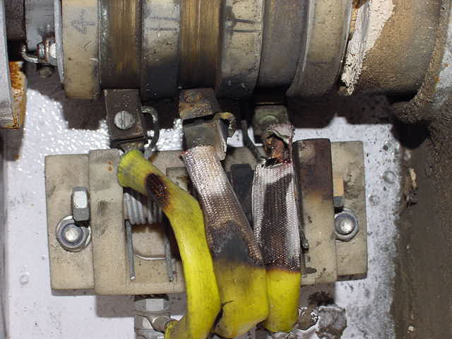
and
the old rings before being tidied up on the lathe.
Altogether it looks like this. It all slides into the yaw head and its done.
With
heaps of grease on the yaw journal.
Now the brushes . This presented a bit of a problem. The old ones had destroyed their springs, were weird shapes. I decided that a starter motor would be a good place to start. This machine is hv, so doesn't require very low resistance brushes..... but i decided brushes designed for 600 cranking amps would probably carry 5-6 amps ok. So I selected one like this:
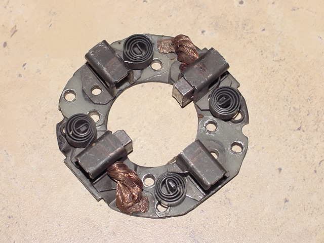
But
the one i used had longer brushes. After I drilled out the rivets, it
looked like this
![]()
But
it allowed me to mount the brush sleeves on strips of steel (cut from
a shipping container 10mm wide), bend and weld and screw em on . It
looks like this:
Jamie
took the blades back to his place and operated on then with epoxy
filler, and sadly I have no pictures of them in their final state.
But they looked good..
So using a few scraps, we have rebuilt the AWP, and it is running very nicely. Jamie rang this morning and it was still air down here. At his place you could barely feel the breeze apparently, and it was putting 1-2 amps into the 48v bank. Later on, the wind picked up and it is putting it's usual 18-24amps into the bank. The blades are very quite again, and the system seems happy.
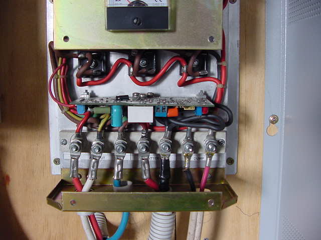
Here is a pic of the inverter:
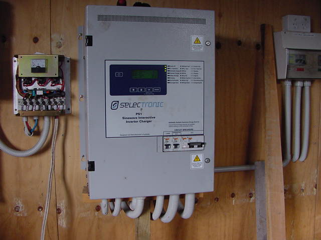
The inverter logs all incoming power and outgoing. It
knows how much came from solar, diesel, wind, for days, months, years
etc. It turns on the genny if it needs to and turns on the genny for
equalisation charge if it sees fit. It can drive welders, pumps,
induction motors up to 3hp...... it's a damn fine unit.
a pic of the dump controller which has worked perfectly from day 1 so AWP got this part right.. no mix ups here.
Idle Curosity.... I only have single phase here, but my machinery is all three phase. Heres a shot of some of the machines with the home brew 3 phase converter in the front:
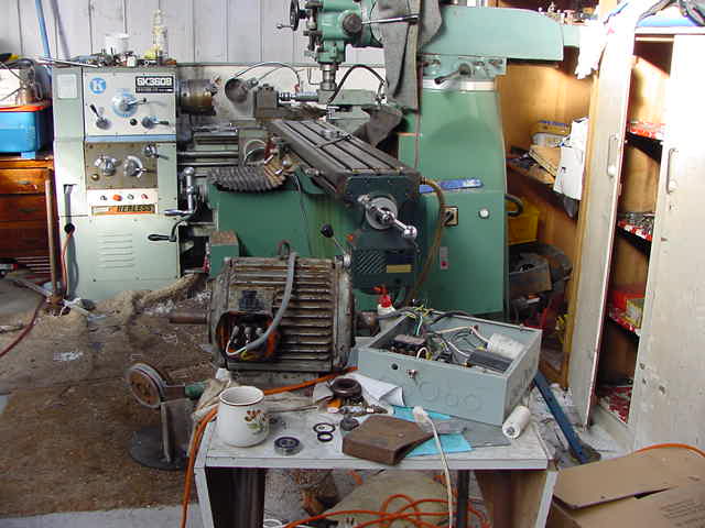
The
rotary converter does not include the axe head... (unless it doesn't
work properly). So all those machines run on that orange extension
cord running up onto the table. The motors in the lathe and Mill and
the Brake press were all opened up and the star point found, I
converted them all from 415 v star to 240v delta. The phase box just
consists of a starter relay, run relay and a bunch of caps. This
allows you to run your three phase gear from single phase no problems
and good three phase stuff is usually much cheaper to buy than good
single phase stuff. And earth leakage detectors are incorporated at
the business end
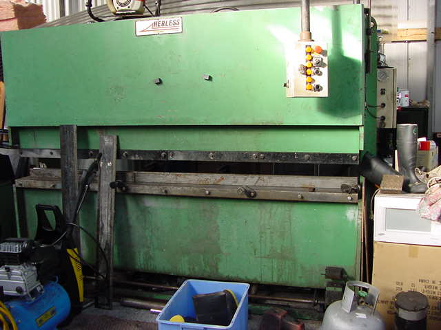
When it all gets too hard, I resort to brute force....the brake press. There is a guillotine to match, but not on single phase yet. It has a very very heavy flywheel and a 10hp motor..... far to much start torque for the converter to even contemplate... another fix in the wings for that.
.............oztules
............